Electricity storage unit

a technology of electric storage unit and storage unit, which is applied in the direction of battery/fuel cell propulsion, battery/cell control arrangement, transportation and packaging, etc., can solve the problems of power transmission loss, increase in the number of components, increase in weight, etc., and achieve the effect of suppressing the influence of nois

Active Publication Date: 2017-11-30
AUTONETWORKS TECH LTD +2
View PDF11 Cites 15 Cited by
  • Summary
  • Abstract
  • Description
  • Claims
  • Application Information

AI Technical Summary

Benefits of technology

[0027]According to the present invention, it is possible to suppress the influence of nois...

Problems solved by technology

In the case where an electrical connection box and a power storage element are installed separately from each other in a vehicle or the like, electrical wires and connectors are needed in order to...

Method used


Image

  • Electricity storage unit
  • Electricity storage unit
  • Electricity storage unit

Examples


embodiment

[0046]An embodiment will be described below with reference to FIGS. 1 to 18.

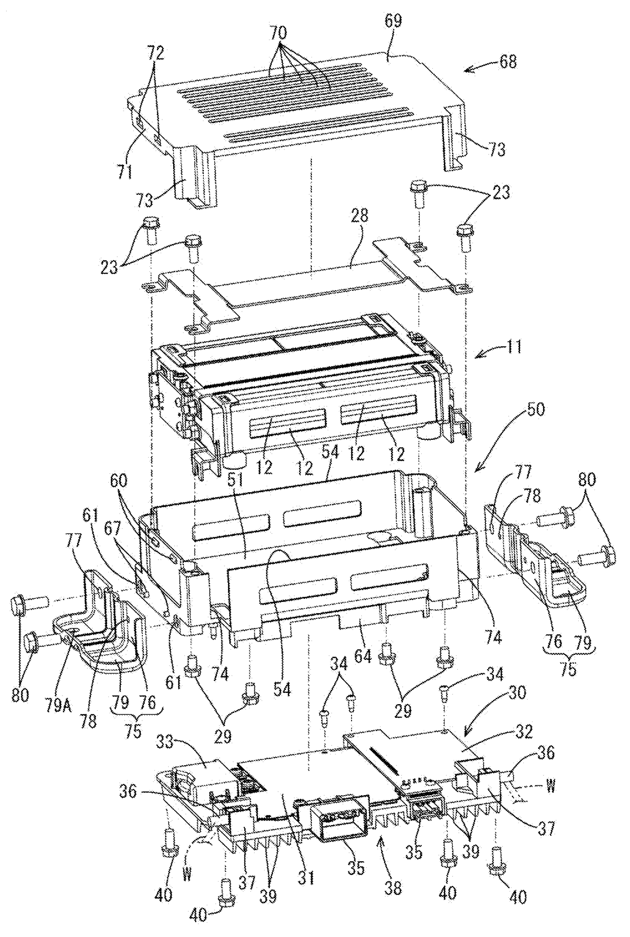
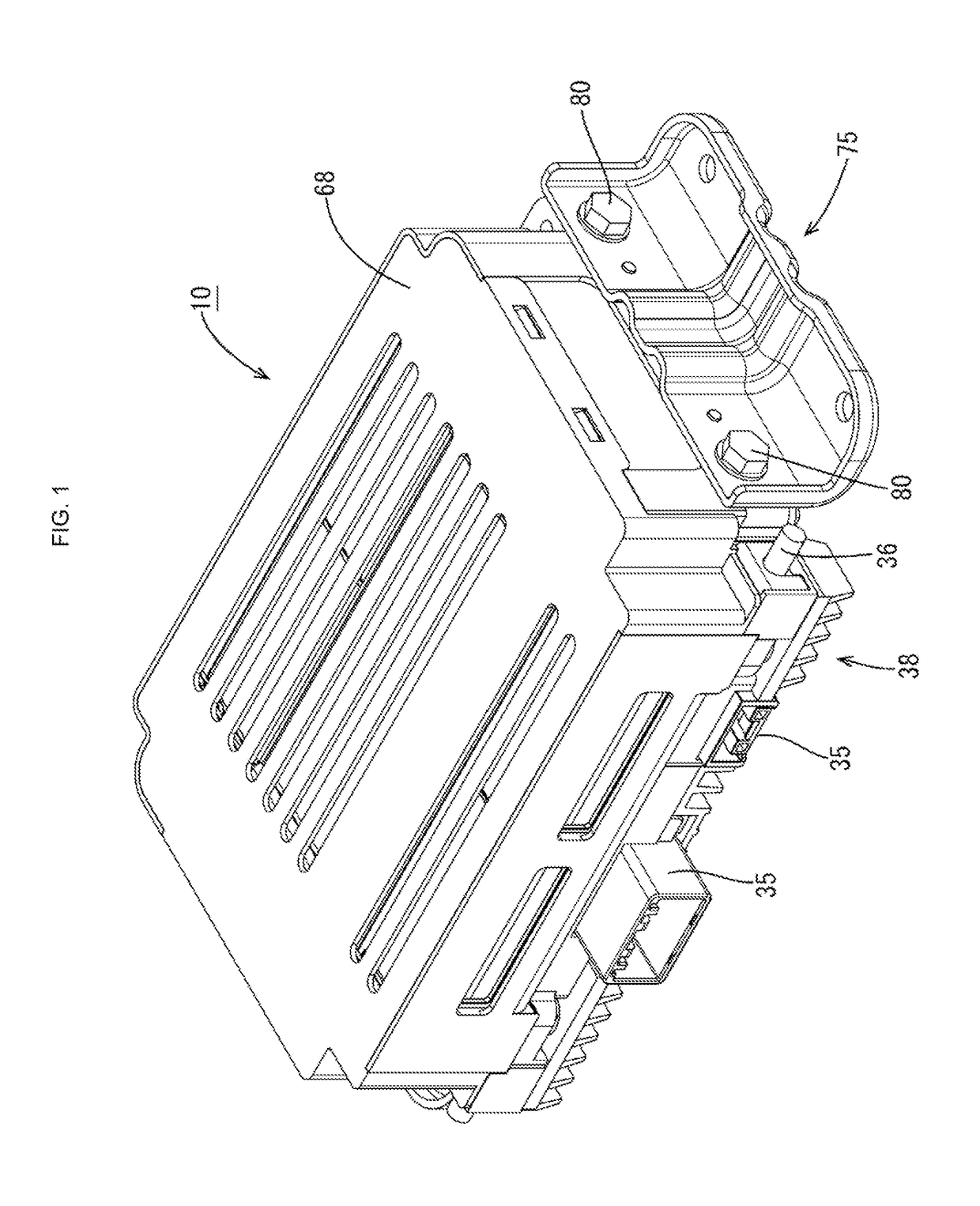
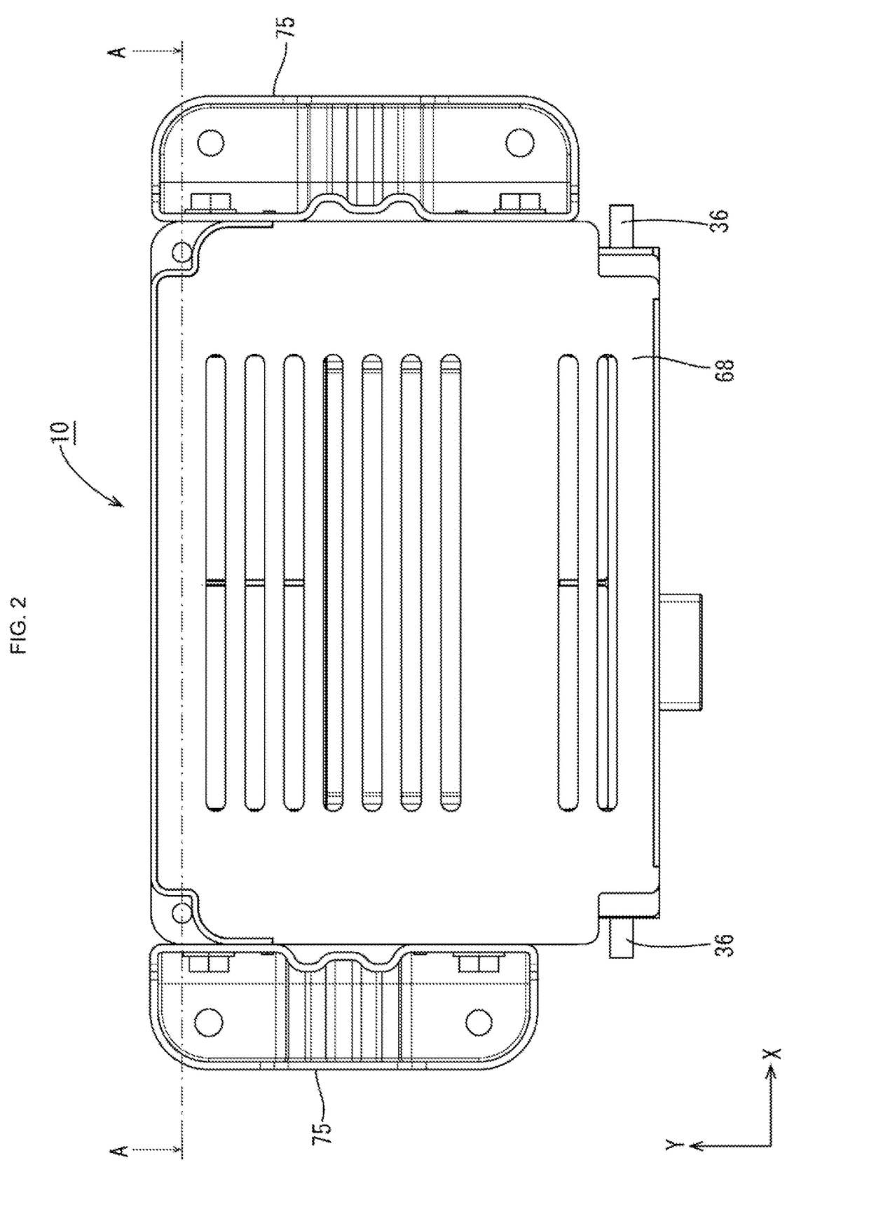
[0047]An electricity storage unit 10 (FIG. 1) is arranged in a power supply path between a main power supply, which is constituted by a battery or the like of a vehicle such as an electric automobile or a hybrid automobile, and a load constituted by a drive motor or an in-vehicle electrical component such as a lamp, for example, and the electricity storage unit 10 can be used as a charging / discharging control apparatus and an auxiliary power supply during engine idling stop and engine restart, for example. In the following description, the vertical direction and the horizontal direction are based on FIG. 4 (the X direction being the rightward direction, and the Z direction being the upward direction), and the front-rear direction is based on the downward direction in FIG. 2 being the frontward direction and the upward direction (Y direction) being the rearward direction.

[0048]Electricity Storage Unit 10

[0049...


PUM


Abstract

The present invention provides an electricity storage unit in which the influence of noise from a circuit portion can be suppressed, and the circuit portion and a power storage element can be consolidated. The electricity storage unit includes a circuit portion on which an electronic component is mounted, power storage elements, and a holding member that holds the power storage elements. The holding member includes an electrically conductive shield wall portion between the circuit portion and the power storage elements, and the shield wall portion shields noise generated by the circuit portion. The electricity storage unit may further have an electrically conductive heat dissipation member that dissipates heat from the circuit portion.

Description

TECHNICAL FIELD[0001]The present specification discloses technology that includes a circuit portion and a power storage element.BACKGROUND ART[0002]Conventionally, an electrical connection box is known in which a circuit portion having electronic components mounted thereon is housed inside a case. Patent Document 1 discloses an electrical connection box that includes a circuit portion having an electronic component mounted thereon, an electrically conductive heat dissipation member that dissipates heat from the circuit portion, and an electrically conductive case that, along with the heat dissipation member, houses the circuit portion. The case that covers the circuit portion is connected to a vehicle ground via a relay ground terminal, and electromagnetic noise generated by high-speed switching of the electronic component or the like is shielded by the case.[0003]In the case where an electrical connection box and a power storage element are installed separately from each other in a...

Claims


Application Information

Patent Timeline
IPC IPC(8): B60R16/023H05K9/00H02G3/08
CPCB60R16/0239H05K9/0003H02G3/08H01G11/10B60L2240/545H02M7/003H02J7/0042B60L58/26B60L50/64H01G11/82Y02T10/70H05K7/14322H05K7/20854H02J7/345H05K7/1432
Inventor SUMIDA, TATSUYAMORITA, KYOHEIKITAGAWA, KAZUHIDEHATTORI, HISAO
Owner AUTONETWORKS TECH LTD
Why Eureka
Try Eureka