Radial-loading Magnetic Reluctance Device

Inactive Publication Date: 2017-11-30
WALSH RAYMOND JAMES
View PDF4 Cites 3 Cited by
  • Summary
  • Abstract
  • Description
  • Claims
  • Application Information

AI Technical Summary

Benefits of technology

[0018]The function of the magnetic assemblies may be enhanced by iron or ferromagnetic flux-focusing elements attached to the magnetic poles of the circular magnetic assemblies and/or the magnet arrays.
[0019]In the same vein as a Halbach array, an array of three consecutive magnets can effectively focus magnetic flux so that north and south poles extend parallel to each other from the s

Problems solved by technology

Pulling on either is initially easy but becomes harder the more

Method used


Image

  • Radial-loading Magnetic Reluctance Device
  • Radial-loading Magnetic Reluctance Device
  • Radial-loading Magnetic Reluctance Device

Examples


Embodiment Construction

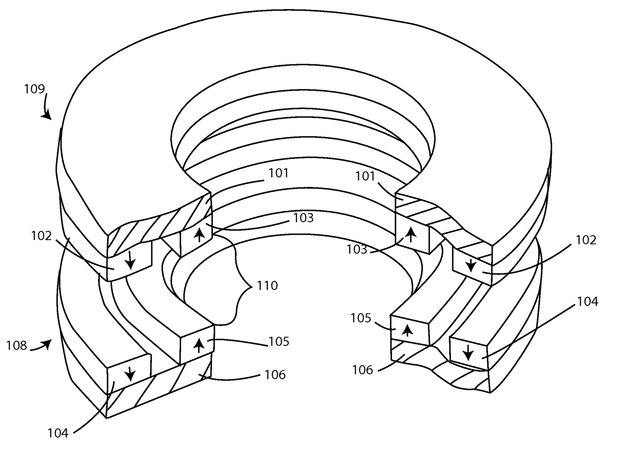
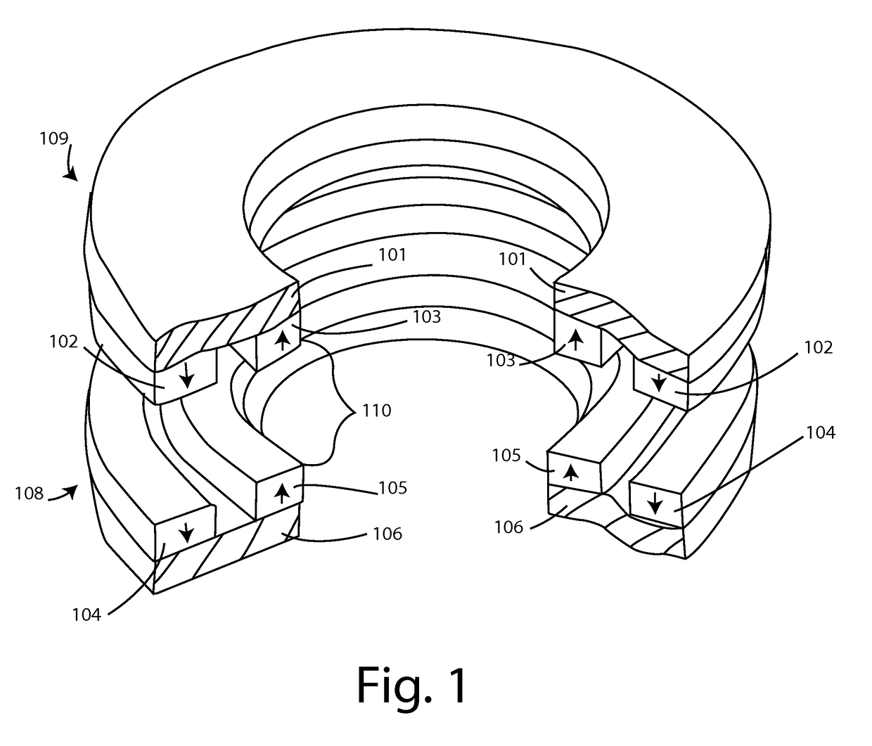
[0023]FIG. 1 is a perspective view of one embodiment a magnetic bearing.

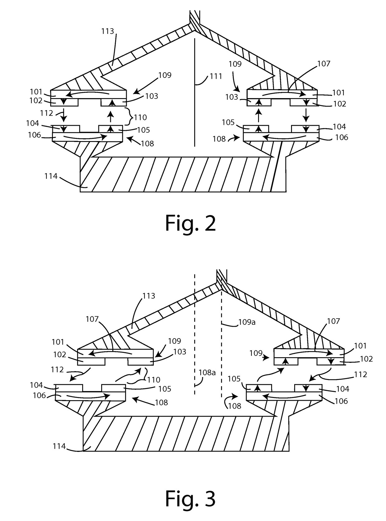
[0024]FIG. 2 is a side view schematic of a magnetic bearing in a state of minimal reluctance.

[0025]FIG. 3 is a side view schematic of the same magnetic bearing but in a position of increased reluctance.

DETAILED DESCRIPTION OF A PREFERRED EMBODIMENTS

[0026]While the presently disclosed inventive concept(s) is susceptible of various modifications and alternative constructions, certain illustrated embodiments thereof have been shown in the drawings and will be described below in detail. It should be understood, however, that there is no intention to limit the inventive concept(s) to the specific form disclosed, but, on the contrary, the presently disclosed and claimed inventive concepts) is to cover all modifications, alternative constructions, and equivalents falling within the spirit and scope of the inventive concept(s) as defined in the claims.

[0027]In order that the invention may be more fully understood, it wi...


PUM


Abstract

A magnetic bearing retains a rotatable shaft in a selected position by magnetic coupling between two circularmagnetic assemblies, one of which is connected to the shaft. Each magnetic coupling completes a magnetic circuit. Shaft rotation does not affect the magnetic circuit, but radial displacement of the shaft disrupts the magnetic circuit and increases magnetic reluctance. Increasing magnetic reluctance inhibits radial displacement. The shaft thereby supports a load while rotating freely, constrained to a selected position by forces of magnetic reluctance. A bearing may be employed to maintain gap distance between the magnetic assemblies.

Description

PRIORITY / CROSS-REFERENCE TO RELATED APPLICATIONS[0001]This application claims the benefit of U.S. Provisional Application No. 61 / 991,642, filed May 12, 2014, the disclosure of which is incorporated by reference.TECHNICAL FIELD[0002]The disclosed technology generally relates to bearings, and more particularly to magnetic bearings.BACKGROUND[0003]A bearing is a machine element that both reduces friction and constrains motion between moving parts. Many types of bearings exist, but the greatest reduction in friction occurs when a magnetic bearing is employed, which supports a load using magnetic levitation. Magnetic bearings permit relative motion with very low friction and mechanical wear, and thus support the highest speeds of all kinds of bearing.[0004]Some magnetic bearings use permanent magnets and do not require input of power, but do require external stabilization due to the limitations described by Earnshaw's Theorem. Most magnetic bearings use attraction or repulsion to achieve...

Claims


Application Information

Patent Timeline
IPC IPC(8): F16C32/04
CPCF16C32/0431F16C32/0425F16C2361/55F16C39/063F16C32/0414F16C32/0417F16C32/0421
Inventor WALSH, RAYMOND JAMES
Owner WALSH RAYMOND JAMES
Why Eureka
Try Eureka