Organic light-emitting device comprising host, phosphorescent dopant and fluorescent dopant

Active Publication Date: 2017-11-30
SEOUL NAT UNIV R&DB FOUND
View PDF55 Cites 19 Cited by
  • Summary
  • Abstract
  • Description
  • Claims
  • Application Information

AI Technical Summary

Benefits of technology

[0023]When a combination of a hole transporting host and an electron transporting host which form an exciplex, or a delayed fluorescent organic compound is used as a host in an emission layer, and such a host i

Problems solved by technology

In conventional fluorescent organic light-emitting devices using a host and a fluorescent dopant, only singlet excitons, which are formed at a ratio of 25% of excitons generated under electrical excitation condition, a

Method used


Image

  • Organic light-emitting device comprising host, phosphorescent dopant and fluorescent dopant
  • Organic light-emitting device comprising host, phosphorescent dopant and fluorescent dopant
  • Organic light-emitting device comprising host, phosphorescent dopant and fluorescent dopant

Examples


Example

[0075]Experimental Example

[0076]FIG. 3 shows photoluminescence spectra of a TCTA thin film, a B4PYMPM thin film, and a TCTA:B4PYMPM thin film. The TCTA:B4PYMPM thin film is a thin film in which TCTA and B4PYMPM were mixed at a ratio (molar ratio) of 1:1. The photoluminescence spectra of the TCTA thin film and the B4PYMPM thin film were each measured at temperature of about 295 K, and the photoluminescence spectrum of the TCTA:B4PYMPM film were measured at two different temperatures of about 295 K and 30 K. The thin films were excited using light at a wavelength of about 355 nm from a Nd:YAG laser (Continuum), and then wavelength-dependent photoluminescence of the thin films was detected by an intensified charge-coupled device (iCCD), thereby measuring photoluminescence spectra of the thin films. Referring to FIG. 3, the photoluminescence spectrum of the TCTA:B4PYMPM thin film appeared in the longer wavelength range, compared to the spectra of the TCTA thin film and the B4PYMPM film....

Example

Example 1

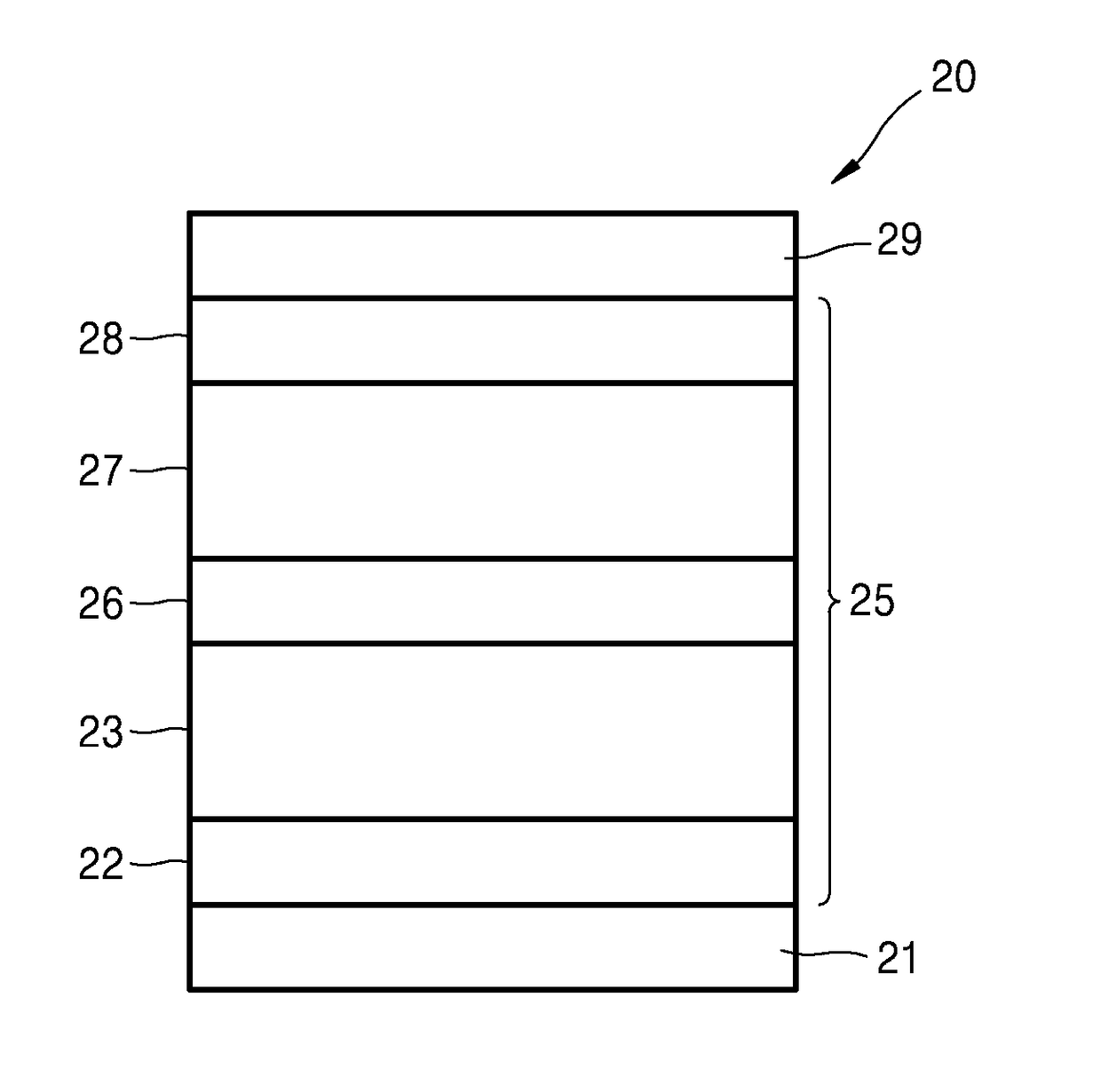
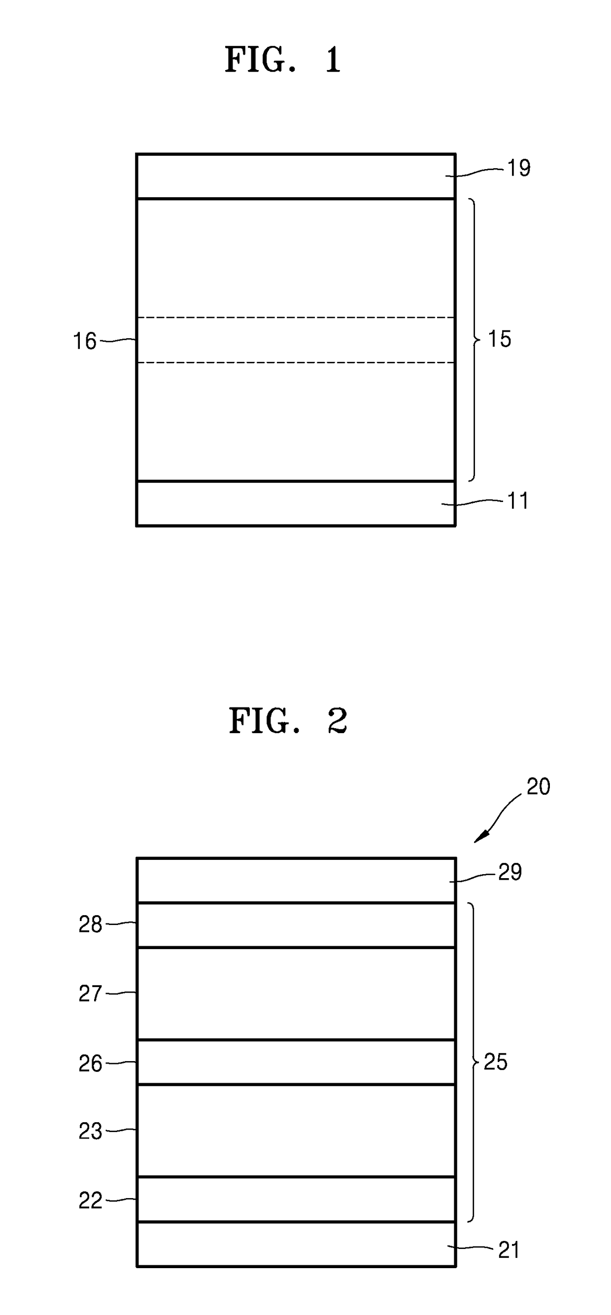
[0083]1,000 Å-thick-patterned ITO which is on a glass substrate, was used as an anode. The ITO glass substrate was pre-washed with isopropyl alcohol and acetone, and then was exposed to UV-ozone for 10 minutes. Next, TAPC was deposited on the ITO glass substrate to form a hole injection layer having a thickness of 650 Å. TCTA was deposited on the hole injection layer to form a hole transport layer having a thickness of 100 Å. Then, (TCTA:B4PYMPM):Ir(ppy)3:DCJTB, wherein a molar ratio of TCTA to B4PYMPM was maintained to 1:1, was co-deposited on the hole transport layer at a weight ratio of 97.5:2:0.5 to form an emission layer having a thickness of 300 Å. Then, B4PYMPM was deposited on the emission layer to form an electron transport layer having a thickness of 550 Å. Next, LiF was deposited on the electron transport layer to form an electron injection layer having a thickness of 7 Å, and then Al was deposited thereon to form a cathode having a thickness of 1,000 Å. Here, ea...

Example

Example 2

[0084]An organic light-emitting device of Example 2 was prepared in the same manner as in Example 1, except that in forming the emission layer, (TCTA:B4PYMPM):Ir(ppy)3:DCJTB were co-deposited at a weight ratio of 95.5:4:0.5 instead of a weight ratio of 97.5:2:0.5.


PUM

PropertyMeasurementUnit
Energyaaaaaaaaaa
Energy levelaaaaaaaaaa

Abstract

According to an aspect, an organic light-emitting device includes: a first electrode; a second electrode facing the first electrode; and an emission layer disposed between the first electrode and the second electrode and including a host and a dopant, wherein the host is an exciplex host, which is a combination of a hole transporting host and an electron transporting host which form an exciplex, or a delayed fluorescent organic compound, and the dopant includes both a phosphorescent dopant and a fluorescent dopant.

Description

TECHNICAL FIELD[0001]The present invention relates to an organic light-emitting device, and more particularly, to an organic light-emitting device including a host, a phosphorescent dopant, and a fluorescent dopant.BACKGROUND ART[0002]In conventional fluorescent organic light-emitting devices using a host and a fluorescent dopant, only singlet excitons, which are formed at a ratio of 25% of excitons generated under electrical excitation condition, are emitted, thereby failing to obtain a high efficiency. Meanwhile, in phosphorescent organic light-emitting devices using a phosphorescent dopant instead of a fluorescent dopant, all singlet and triplet excitons can be subjected to conversion to generate light, thereby achieving a high efficiency. However, due to high prices of a phosphorescent dopant, it is disadvantageous to use phosphorescent organic light-emitting devices in terms of an economic aspect. In this regard, there are ongoing studies of a delayed fluorescent dopant, which ...

Claims


Application Information

Patent Timeline
IPC IPC(8): H01L51/50H01L51/00C09K11/06C09K11/87
CPCH01L51/5004H01L51/5024H01L51/5072C09K11/87H01L51/0035C09K11/06H01L51/5056C09K2211/185H10K85/654H10K85/342H10K50/11H10K2101/10H10K2101/27H10K2101/90H10K2101/20H01L2924/12044H10K50/12H10K50/15H10K50/16H10K85/111H10K2101/40
Inventor KIM, JANG-JOOKIM, HYUN-GUKIM, KWON-HYEONSUN, JIN-WON
Owner SEOUL NAT UNIV R&DB FOUND
Why Eureka
Try Eureka