

Ink composition, light conversion layer, and color filter
- Summary
- Abstract
- Description
- Claims
- Application Information
AI Technical Summary
Benefits of technology
Problems solved by technology
Method used
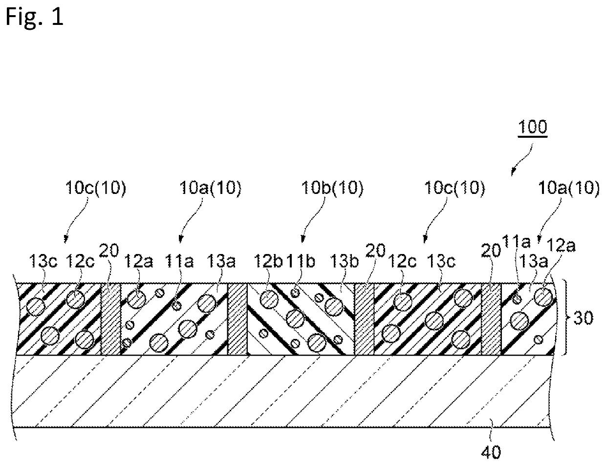
Image

Examples
example 1
[Preparation of Red Ink Composition (Ink Jet Ink)]
[0184]The red-light-emitting nanocrystalline particle dispersion 1, the light-scattering particle dispersion 1, a photopolymerization initiator Omnirad TPO-H (2,4,6-trimethylbenzoyl-diphenyl-phosphine oxide, manufactured by IGM resin, trade name, molecular weight: 316), and a phosphite compound JP-333E were uniformly mixed in a vessel filled with argon gas. The component contents of the ink composition were shown in Table 2. The mixture was then passed through a filter with a pore size of 5 μm in a glove box. Argon gas was introduced into a vessel containing the filtrate to saturate the vessel with argon gas. Thus, an ink composition of Example 1 was prepared. The light-emitting nanocrystalline particle content in Table 2 includes the organic ligand content.
example 16
[0186]An ink composition of Example 16 was prepared in the same manner as in Example 8 except that the red-light-emitting nanocrystalline particle dispersion 2 and the light-scattering particle dispersion 2 were used instead of the red-light-emitting nanocrystalline particle dispersion 1 and the light-scattering particle dispersion 1.
example 17
[0187]An ink composition of Example 17 was prepared in the same manner as in Example 8 except that the red-light-emitting nanocrystalline particle dispersion 3 and the light-scattering particle dispersion 3 were used instead of the red-light-emitting nanocrystalline particle dispersion 1 and the light-scattering particle dispersion 1.
PUM
| Property | Measurement | Unit |
|---|---|---|
| Temperature | aaaaa | aaaaa |
| Pressure | aaaaa | aaaaa |
| Hansen parameter | aaaaa | aaaaa |
Abstract
Description
Claims
Application Information