Supercharge Your Innovation With Domain-Expert AI Agents!

Switchable interface for chargers

a charger and switchable technology, applied in parallel/serial switching, battery data exchange, transportation and packaging, etc., can solve the problems of high cost, no longer having original capacity, and new rechargeable batteries not identical to the old, i.e., original, rechargeable batteries, etc., to achieve simple and reliable recognition and simple design

Active Publication Date: 2017-11-30
HILTI AG
View PDF5 Cites 2 Cited by
  • Summary
  • Abstract
  • Description
  • Claims
  • Application Information

AI Technical Summary

Benefits of technology

The present invention provides a charging device for a rechargeable battery that improves compatibility between the battery and the charger. The device has an interface device with multiple terminal points that can be set in different positions to charge different types of batteries. The interface device can also have a connection point with multiple terminal elements for connecting it to a control device. The interface device and the battery can be easily recognized based on the number of connections. The interface device can also have terminal elements designed to receive information about the respective battery and set the charging configuration accordingly, making it easy for the charger to charge the chosen battery.

Problems solved by technology

The rechargeable battery undergoes high stress due to continued use and in particular due to frequent charging, so that after a certain period of time it no longer has its original capacity.
However, since the machine tool and the charger do not necessarily also have to be replaced along with the rechargeable battery, the problem often arises that the new rechargeable battery is not identical to the old, i.e., original, rechargeable battery.
As the result of development measures, it is possible that the new rechargeable battery includes a new electromechanical interface device which, although it is compatible with the machine tool, is incompatible with the original charger.
In addition, it is possible that, as the result of such development measures for the rechargeable battery charger, a new charger that is intended to replace the original charger due to signs of wear is not compatible with an older rechargeable battery.
This may result in an incompatibility problem between the rechargeable battery and the charger.

Method used


Image

  • Switchable interface for chargers
  • Switchable interface for chargers
  • Switchable interface for chargers

Examples


second specific embodiment

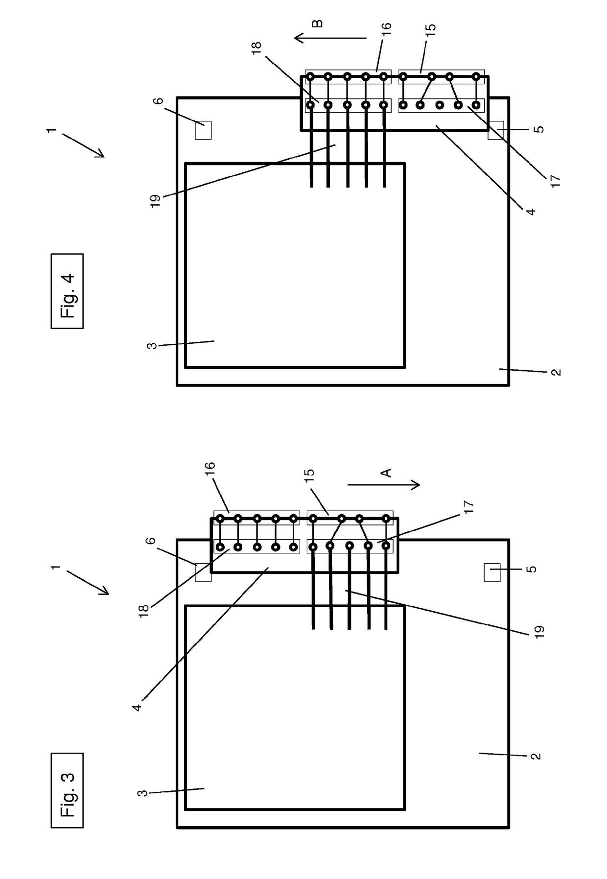
[0048]FIGS. 3 and 4 illustrate charging device 1. Charging device 1 according to the second specific embodiment is essentially identical to charging device 1 according to the first specific embodiment. In FIG. 3, interface device 4 is in the first position, and in FIG. 4, interface device 4 is in the second position. In contrast to the first specific embodiment, charging device 1 according to the second specific embodiment is configured in such a way that interface device 4 may be reversibly brought from the first position into the second position by a displacement. For changing interface device 4 from the first position into the second position, interface device 4 is moved in direction A relative to housing 2 of charging device 1 (see FIG. 3). For returning interface device 4 from the second position into the first position, interface device 4 is moved in direction B relative to housing 2 of charging device 1 (see FIG. 4).

third specific embodiment

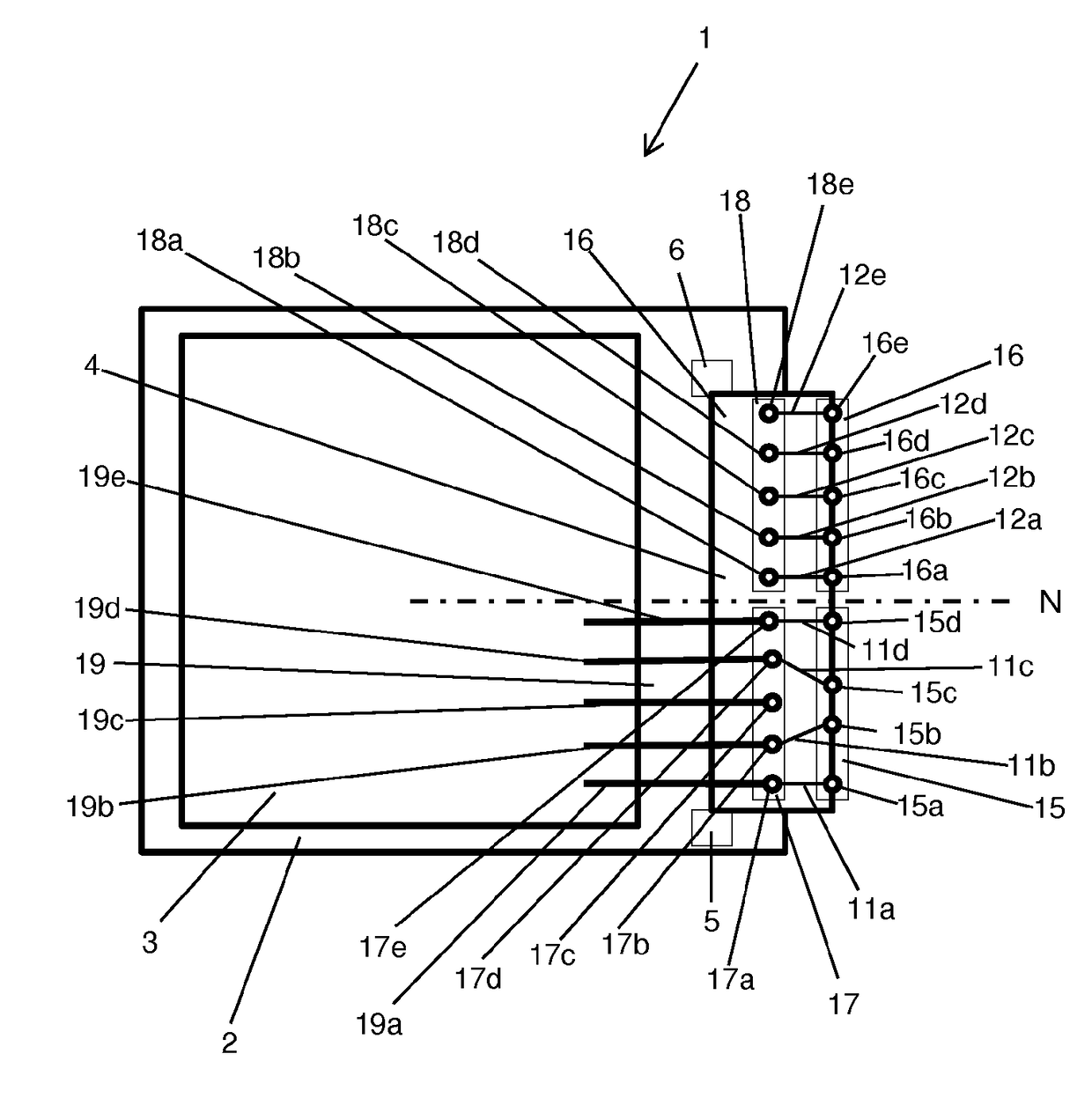
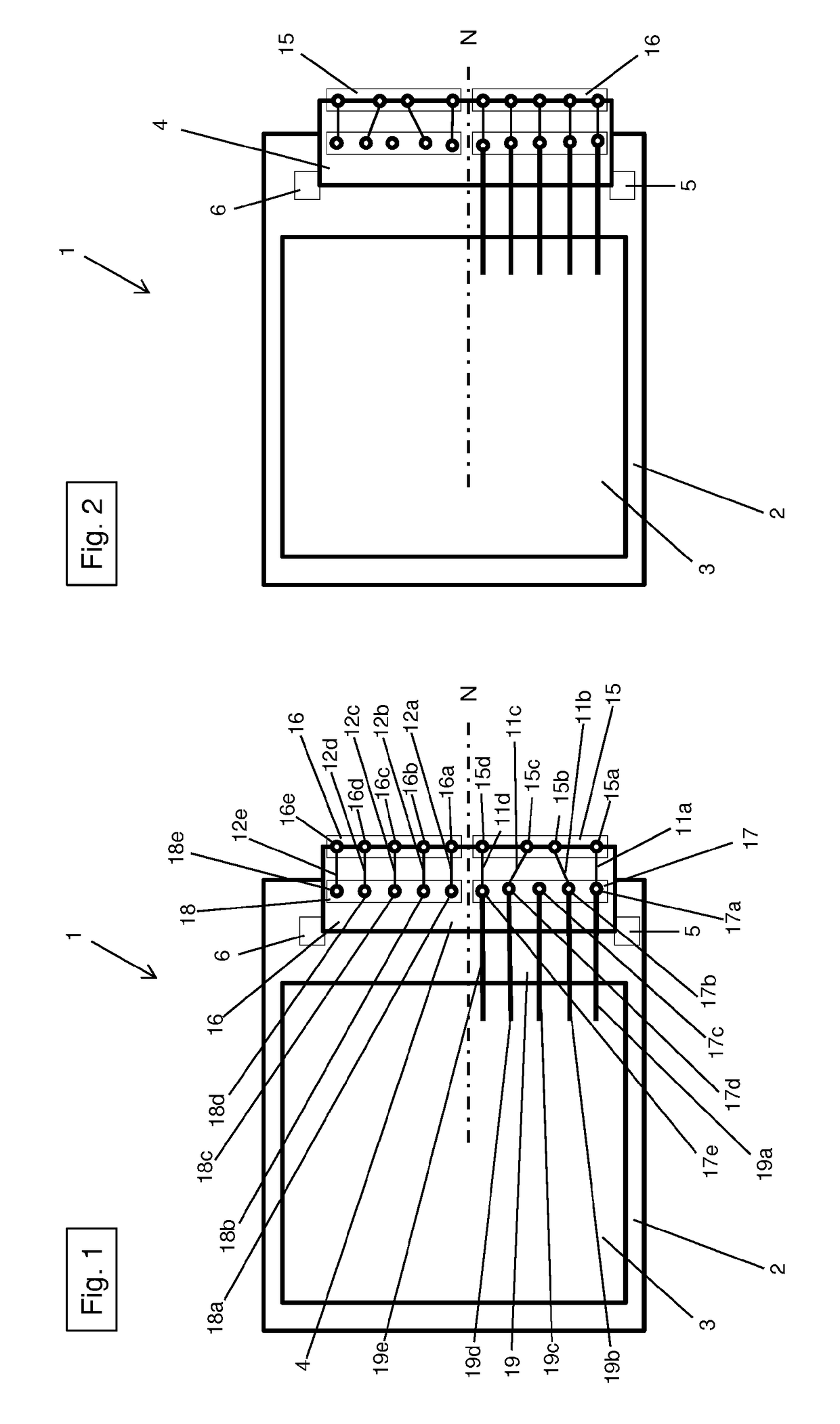
[0049]FIGS. 5 and 6 illustrate charging device 1. According to the third specific embodiment and in contrast to the first specific embodiment, interface device 4 is designed in the shape of a cube. Only a first side 14a, a second side 14b, a third side 14c, and a fourth side 14d are illustrated in Figures and 6. Interface device 4 contains a first terminal point 15, a second terminal point 16, a first connection point 17, and a second connection point 18. As shown in FIG. 5, first terminal point 15 is positioned on first side 14a of interface device 4, designed as a cube. First connection point 17 is positioned on second side 14b of the cube. Second terminal point 16 is positioned on third side 14d of the cube. Second connection point 18 is positioned on third side 14c of the cube. First terminal point 15 contains four terminal elements 15a, 15b, 15c, 15d, and second terminal point 16 contains five terminal elements 16a, 16b, 16c, 16d, 16e. First connection point 17 contains four co...

fourth specific embodiment

[0053]FIGS. 7 and 8 illustrate charging device 1. According to the fourth specific embodiment and in contrast to the first specific embodiment, interface device 4 is likewise designed in the shape of a cube.

[0054]Only a first side 14a, a second side 14b, a third side 14c, and a fourth side 14d are illustrated in FIGS. 7 and 8. Interface device 4 contains a first terminal point 15, a second terminal point 16, and a connection point 17. As shown in FIG. 7, first terminal point 15 is positioned on first side 14a of interface device 4, designed as a cube. Second terminal point 16 is positioned on second side 14b of the cube. Connection point 17 is positioned on third side 14c of the cube. According to the fourth specific embodiment, charging device 1 includes a control device 3 with only one connection device 19 together with five connecting lines 19a, 19b, 19c, 19d, 19e. The five connecting lines 19a, 19b, 19c, 19d, 19e are connected to the five connecting elements 17a, 17b, 17c, 17d, ...


PUM


Abstract

Disclosed is a charger for charging a rechargeable battery, comprising a control device and at least one electromechanical interface device for connecting at least one rechargeable battery to the charger and supplying a voltage to said battery. The interface device comprises at least a first terminal and a second terminal and can be set to at least one first position and to a second position; the first terminal can be used for charging a first rechargeable battery when the interface is in the first position, and the second terminal can be used for charging a second rechargeable battery when the interface is in the second position.

Description

[0001]The present invention relates to a charging device for charging at least one rechargeable battery, containing at least one electromechanical interface device for connecting at least one rechargeable battery to the charging device and for supplying the rechargeable battery with a voltage, and a control device.BACKGROUND[0002]Electric machine tools such as drill hammers, circular saws, angle grinders, or the like are often supplied with voltage with the aid of a rechargeable battery. The rechargeable batteries are generally configured in such a way that they may be connected to the machine tool and also detached again. The detachable connection between the rechargeable battery and the machine tool is used, among other things, to recharge a rechargeable battery, which has become depleted due to use of the machine tool, with voltage via a rechargeable battery charging device (also referred to as a rechargeable battery charger, or charger). After the rechargeable battery has been r...

Claims


Application Information

Patent Timeline
Patent Type & Authority Applications(United States)
IPC IPC(8): H02J7/00H02J7/04
CPCH02J7/0003H02J7/042H02J7/008H02J7/0045H02J7/00045H02J7/0024H02J7/00047
Inventor HUNGER, MARKUS
Owner HILTI AG
Features
  • R&D
  • Intellectual Property
  • Life Sciences
  • Materials
  • Tech Scout
  • Unparalleled Data Quality
  • Higher Quality Content
  • 60% Fewer Hallucinations
Learn More