Projection system and light screen generating device thereof

a technology of projection system and light screen, which is applied in the direction of picture reproducers, picture reproducers using projection devices, instruments, etc., can solve the problems of insufficient uniformity of conventional invisible light screen, inability of detection devices to accurately detect touching locations, and inability to generate signals, etc., to achieve the effect of increasing light emission uniformity

Active Publication Date: 2017-11-30
K LASER TECH +1
View PDF2 Cites 2 Cited by
  • Summary
  • Abstract
  • Description
  • Claims
  • Application Information

AI Technical Summary

Benefits of technology

The present invention provides a projection system with a light screen generating device that prevents the issue of uneven lighting on the projection screen due to excessive darkness. This is achieved by designing multiple light-emitting structures on a movable carrier module that sends out invisible light screens that are then spliced together to create a more uniform light emission. This results in a more seamless and even lighting experience for the audience.

Problems solved by technology

Inversely, if the distance between the invisible light screen and the projection plane appears to be too close, the reflected light beams could easily be blocked by the touching object when users are inputting information by touch on the projection plane, which leads to the light detection device's inability to accurately detect the touching location so that correct touch signals cannot be generated.
However, the conventional invisible light screen has the problem of insufficient uniformity.
Specifically, when the light screen sweeps over the upper section of the left-side portion and the right-side portion of the projection plane, it may be unable to uniformly cover the entire projection area due to excessive darkness.
Therefore, developing modifications that can overcome the abovementioned flaws has become a critical issue in the art.

Method used


Image

  • Projection system and light screen generating device thereof
  • Projection system and light screen generating device thereof
  • Projection system and light screen generating device thereof

Examples


Embodiment Construction

[0025]The aforementioned illustrations and following detailed descriptions are exemplary for the purpose of further explaining the scope of the present disclosure. Other objectives and advantages related to the present disclosure will be illustrated in the subsequent descriptions and appended drawings.

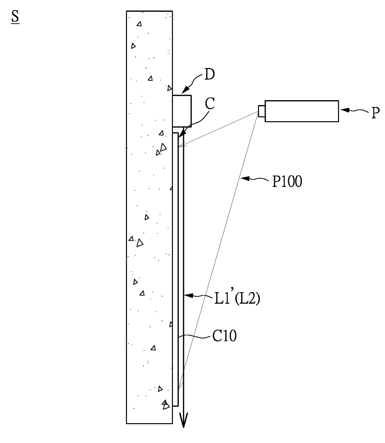
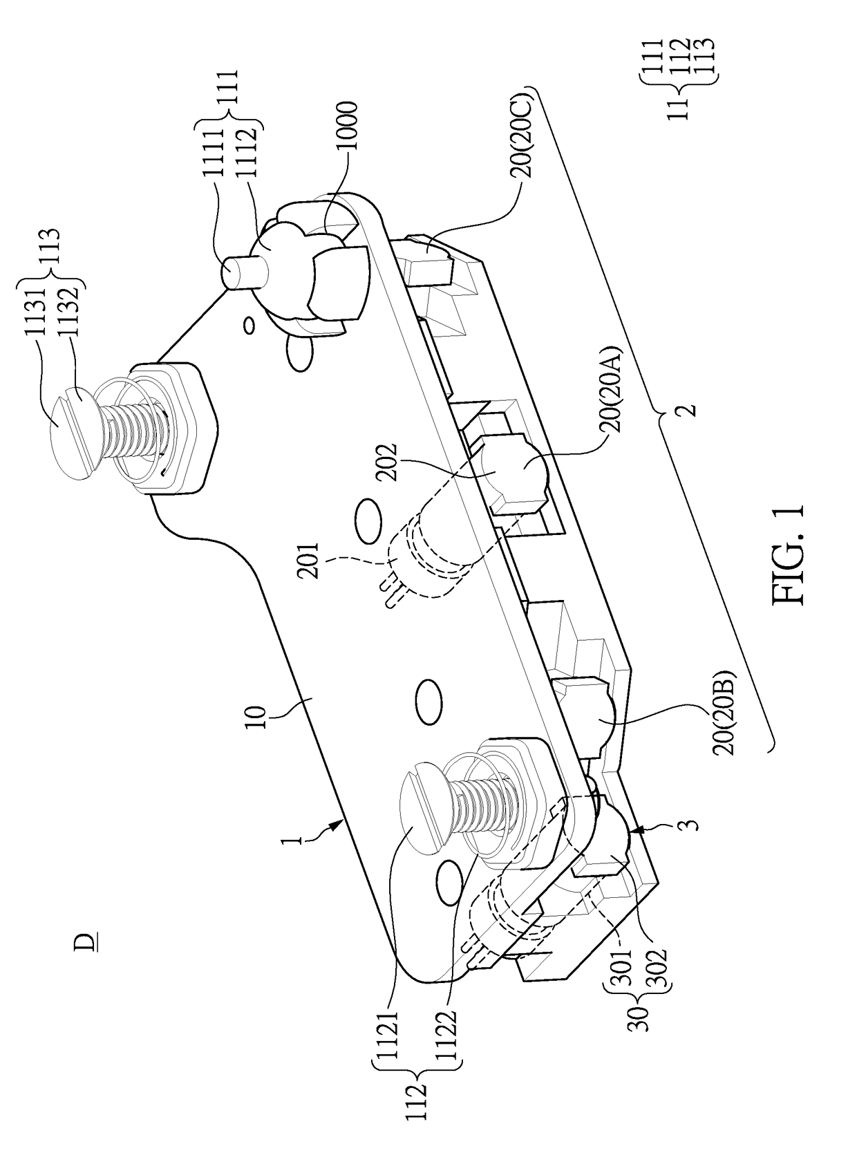
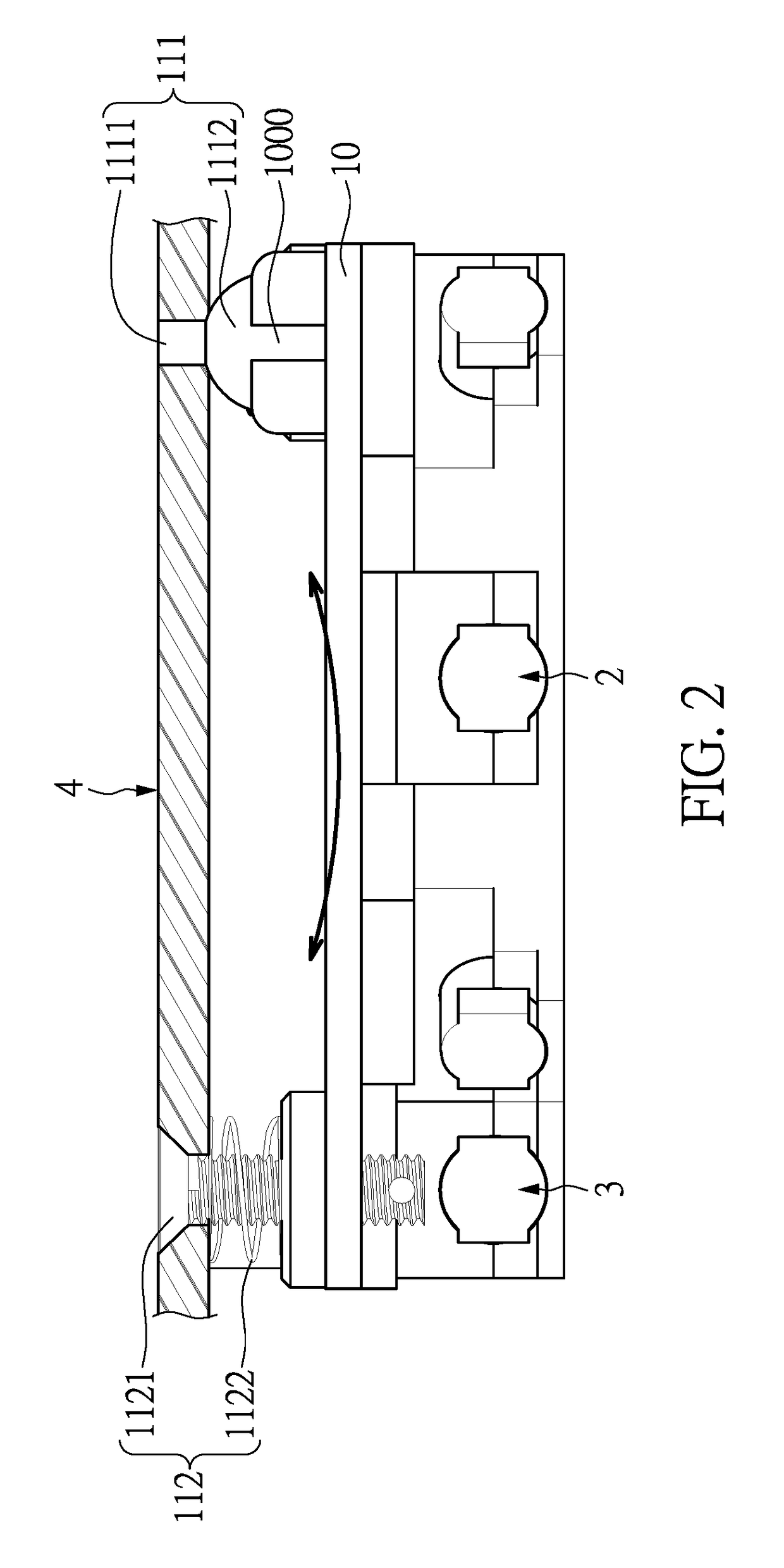
[0026]Referring to FIGS. 1-9, the present disclosure provides a light screen generating device D, which can be applied to a projection screen C, and the projection screen C has a projection area C10. The light screen generating device D includes a movable carrier module 1, a first light-emitting module 2 and a second light-emitting module 3.

[0027]Reference is firstly made to FIG. 1 and FIG. 4. The movable carrier module 1 includes a movable carrier base 10 carrying the first light-emitting module 2 and the second light-emitting module 3, and an adjusting mechanism 11 disposed on the movable carrier base 10. Moreover, the adjusting mechanism 11 includes a pivot structure 111, a levelnes...


PUM


Abstract

The present disclosure provides a projection system and a light screen generating device thereof. The light screen generating device includes a movable carrier module, a first light-emitting module, and a second light-emitting module. The first light-emitting module includes a plurality of first light-emitting structures disposed on the movable carrier module. Each of the first light-emitting structures generates an invisible light screen, and the invisible light screens respectively generated by the first light-emitting structures are mated with each other to form a spliced invisible light screen for increasing light emission uniformity. The second light-emitting module includes a second light-emitting structure that is disposed on the movable carrier module and that generates a visible light screen parallel to and overlapping the spliced invisible light screen.

Description

BACKGROUND OF THE INVENTION1. Field of the Invention[0001]The present disclosure relates to a projection system and a light screen generating device thereof; in particular, to a projection system and a light screen generating device thereof capable of increasing the uniformity of an invisible light screen.2. Description of Related Art[0002]An interactive projection system allows users to perform touching operation on a projection plane. The interactive projection system utilizes an invisible light screen emitted from a light source device to cover the entire projection plane, so as to let the invisible light screen be reflected by a touching object and to generate reflected light beams when users interact with a projection picture on the projection plane, and further to generate a corresponding touch signal by using an invisible light detection device to receive the reflected light beams and to detect the touching location.[0003]The distance between the invisible light screen and th...

Claims


Application Information

Patent Timeline
Patent Type & Authority Applications(United States)
IPC IPC(8): H04N9/31G03B21/56G06F3/042
CPCH04N9/3191G03B2206/00G06F3/0421G03B21/56G03B21/26H04N9/3194
Inventor HONG, HEI-TAISHIH, YUEH-HONGCHEN, CHI-JUNGWEY, GANG-LIANGCHEN, HSIN-CHIN
Owner K LASER TECH
Why Eureka
Try Eureka