Hydroponic plant grow cabinet

a technology for growing cabinets and plants, applied in greenhouse cultivation, climate change adaptation, instruments, etc., can solve the problems of limited automation of existing cabinets and the need for regular maintenan

Active Publication Date: 2017-12-07
NATUFIA LABS OU
View PDF19 Cites 37 Cited by
  • Summary
  • Abstract
  • Description
  • Claims
  • Application Information

AI Technical Summary

Benefits of technology

[0020]Preferably the grow cabinet according to the invention have dimensions corresponding to standard kitchen applian...

Problems solved by technology

However said existing cabinet offers very limited automation and requires regu...

Method used


Image

  • Hydroponic plant grow cabinet
  • Hydroponic plant grow cabinet
  • Hydroponic plant grow cabinet

Examples


Embodiment Construction

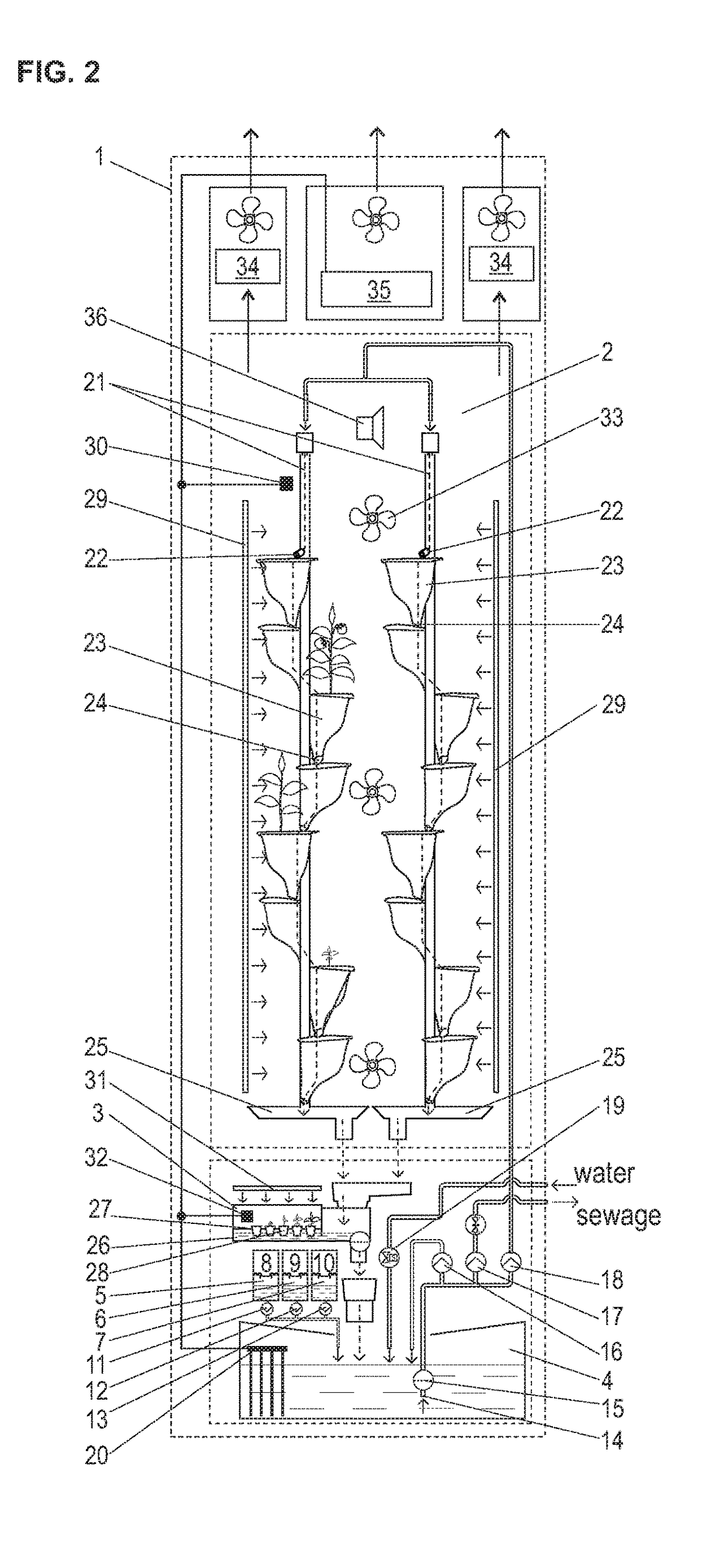
[0025]In the schematic diagrams for the sake of clarity only essential units and devices of the grow cabinet are depicted, therefore a wiring of fans, pumps and valves are omitted from the diagram. Also a wiring of sensors is only depicted in general manner The liquid flow through the cabinet is depicted with dash lines ending with arrow heads.

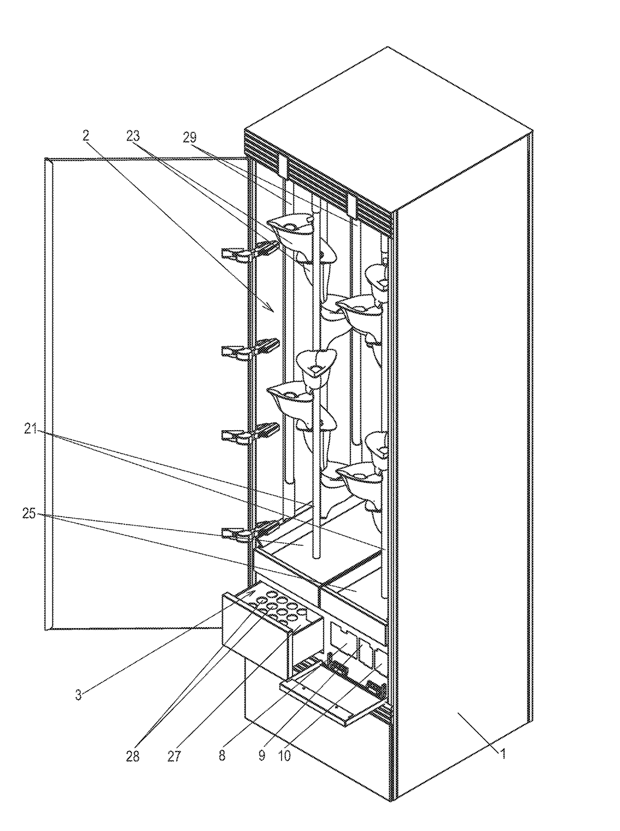
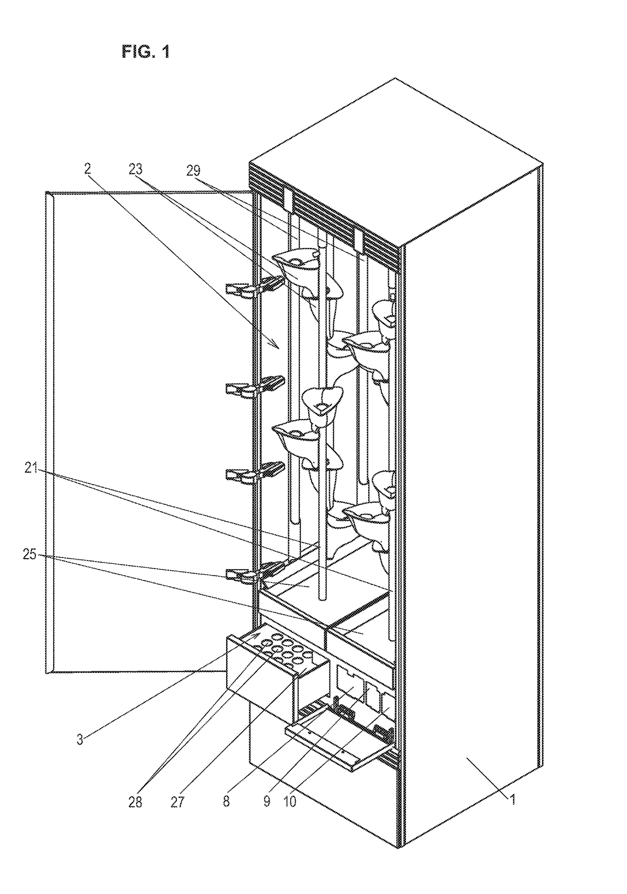
[0026]The hydroponic plant grow cabinet according to present invention comprises a housing 1, said housing 1 comprising main plant growing chamber 2 and a pre-growing chamber 3 for seed / seedlings, main tank 4 and auxiliary tanks 5, 6 and 7.

[0027]The auxiliary tank 5 is for a nutrient solution, the auxiliary tank 6 is for a chemical for regulating pH level up and auxiliary tank 7 is for a chemical for regulating pH level down. On top of the tank 5 sits a refill cartridge 8, on top of the tank 6 sits a refill cartridge 9 and on top of tank 7 sits a refill cartridge 10.

[0028]A module of a refill cartridge system comprises refill cartridges 8, 9 a...


PUM


Abstract

Present invention relates to a hydroponic plant grow cabinet, comprising a housing, said housing comprising main plant growing chamber and a pre-growing chamber for seeds/seedlings, main tank and auxiliary tanks for a nutrient solution and pH level regulating solutions, pumps and tubing, lighting means, ventilating means, control means, sensors, display means, loudspeaker and user input means, network communication means, connection to electric main, connections to water mains and sewage.

Description

TECHNICAL FIELD[0001]Present invention relates to a hydroponic plant grow cabinet. More precisely present invention relates to a home or professional appliance for growing edible plants using fully automated hydroponic technology.BACKGROUND ART[0002]In patent U.S. Pat. No. 5,283,974A (published Aug. 2, 1994) is known a portable grow cabinet, comprising control means for controlling various environmental functions, such as plant watering, temperature, humidity, air circulation and lighting. However said existing cabinet offers very limited automation and requires regular maintenance (for example frequent refilling) and frequent monitoring by the user.DISCLOSURE OF INVENTION[0003]The aim of the present invention is to provide an easy and simple to use fully automated apparatus to grow plants hydroponically in a limited place. Said cabinet is intended for a non-professional growers, i.e. to the end users, as restaurants, offices or private homes.[0004]The aim of the present invention i...

Claims


Application Information

Patent Timeline
IPC IPC(8): A01G31/02G08B21/18A01G9/00A01G31/00
CPCG08B21/18A01G31/02A01G9/24Y02A40/25Y02P60/21A01G2031/006
Inventor LU, GREGORY FRANCIS CHAKWANKAPP, LAURI
Owner NATUFIA LABS OU
Why Eureka
Try Eureka