Cleaning Robot for Tire Curing Mold

Active Publication Date: 2017-12-07
LANG YUZER OTOMOTIV YAN SANAYI VE TICARET ANONIM SIRKETI
View PDF7 Cites 11 Cited by
  • Summary
  • Abstract
  • Description
  • Claims
  • Application Information

AI Technical Summary

Problems solved by technology

This process causes a noise over the limits of business safety for the operator.
Furthermore, displacement of the molds d

Method used


Image

  • Cleaning Robot for Tire Curing Mold
  • Cleaning Robot for Tire Curing Mold
  • Cleaning Robot for Tire Curing Mold

Examples


Embodiment Construction

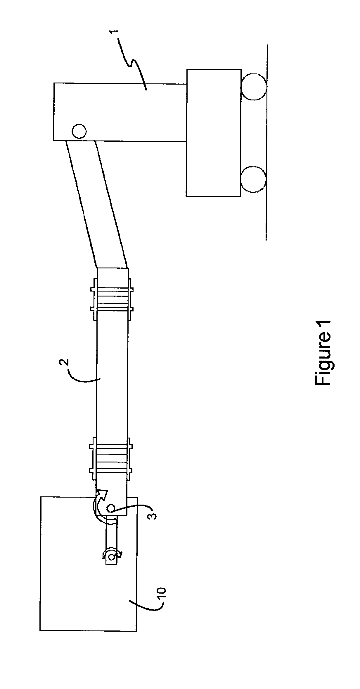
[0021]FIG. 1 shows a cleaning robot from a side view schematically for cleaning the curing tire mold comprising a basket (10) and a carriage (1) is carrying the basket (10). There is a folding arm (2) at the end of the carriage (1). The free end (3) of the folding arm (2) is mounted to the basket (10) via pivot (3).

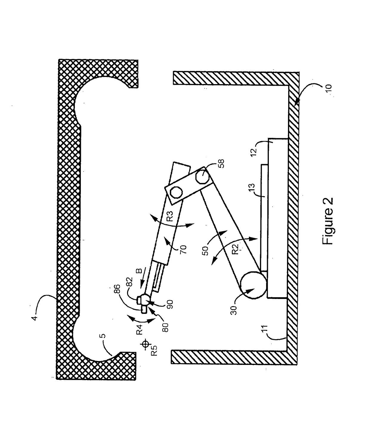
[0022]Position of the basket (10) is shown under a half mold (4) which is one part of a tire curing mold halves in FIG. 2. Half mold (4) is such as having opening from bottom side of the half mold. The peripheral edges of the half mold (4) is combined with in a manner of connection on the frontal plane corresponding above the peripheral edges of the basket (10) as the basket (10) is elevated. Thus, the half-mold (4) and the basket (10) form a closed internal space together.

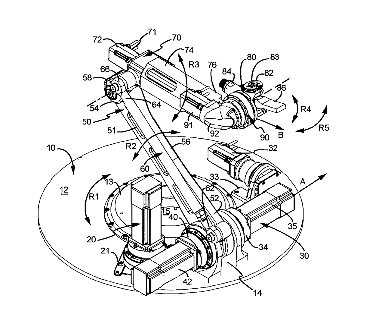
[0023]The cleaning robot is mounted on, at the bottom (11) of the basket (10) placed to a Rotating base (12) in a rotatable manner. Rotating base (12) and the basket (10) is concentric to each other. Al...


PUM

PropertyMeasurementUnit
Angleaaaaaaaaaa
Angleaaaaaaaaaa
Angleaaaaaaaaaa

Abstract

Invention is a cleaning robot for cleaning the inner surfaces (5) of the half mold (4) of tire curing molds comprising a basket (10) wherein a lifting arm (50) placed in a manner pivotal on a proximal end (52), the lifting arm (50) pivoted on a distal end (54) of a support arm (70). The cleaning robot fits completely into the basket (10) when the positioned as close and comprising a movable head (80) having a nozzle (82) coupled in a manner to establish fluid communication to the dry ice inlet (84) and located at the distal end (76) of the support arm (70) and a free end which is configured movably closer to the inner surface (5) such as at a vicinity of the inner surface (5) along the contour of its when the positioned as open.

Description

TECHNICAL FIELD[0001]The invention relates to a robot mechanism for cleaning molds of tire curing used in the production of vehicle tires using dry ice.TECHNICAL BACKGROUND[0002]There are two-part curing molds having one top part of this mold is movable vertically so as to open and one bottom part that are placed on each other and used for the manufacture of vehicle tires. In these molds, vulcanization process (curing) takes place and generally removing of the rubber residuals by cleaning of the threads on tires formed with mold recesses on the top mold part or on the other surfaces and on the bottom mold, and on the side walls.[0003]Dry ice blasting is known for the non-destructive cleaning from a nozzle towards into inner volume of the cleaning mold. This process causes a noise over the limits of business safety for the operator. International patent publication numbered with WO9807548A1, discloses an apparatus and a method using frozen gas pellets by the help of apparatus control...

Claims


Application Information

Patent Timeline
IPC IPC(8): B29D30/06B08B9/00B25J11/00B29C33/72
CPCB29D30/0662B25J11/0085B29D2030/0663B08B9/00B29C33/72B25J9/047B25J18/025
Inventor YUZER, ISMETYUCEL, MUSTAFA HAMIDENIZLI, OKANAL, GORKEM ANILORBAY, LATIF
Owner LANG YUZER OTOMOTIV YAN SANAYI VE TICARET ANONIM SIRKETI
Why Eureka
Try Eureka