Tool for Mounting a Tension Clamp

a technology for mounting tools and clamps, which is applied in the direction of manufacturing tools, wire tools, bundling machine details, etc., can solve the problem that a large part of the wear occurs on the buckle rather than on the tool

Active Publication Date: 2017-12-07
OETIKER SCHWEIZ AG
View PDF3 Cites 5 Cited by
  • Summary
  • Abstract
  • Description
  • Claims
  • Application Information

AI Technical Summary

Benefits of technology

[0010]The severing device for shearing off the band preferably has a shearing member movable in a direction transverse to the longitudinal direction of the band wherein the shearing member, in shearing off the band, cooperates with a part of the buckle so that part of the wear takes place on the buckle rather than on the tool also in this process. The edge of the shearing member facing the buckle is rounded off to avoid abrasion of material (e.g. of a coating) when he tension clamp is inserted.
[0011]In an embodiment, the severing device has two counter-acting plier jaws with cutting e

Problems solved by technology

Part of the occurring wear thus takes pla

Method used


Image

  • Tool for Mounting a Tension Clamp
  • Tool for Mounting a Tension Clamp
  • Tool for Mounting a Tension Clamp

Examples


Embodiment Construction

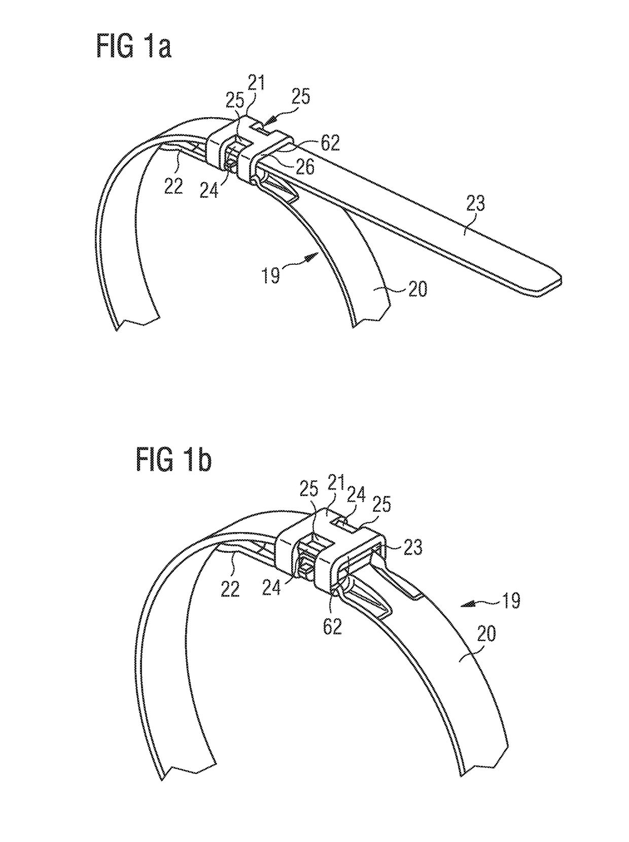
[0026]The tension clamp 19 shown in FIGS. 1a and 1b of the drawings includes a band 20 and a buckle 21. Both parts are preferably made of metal. FIG. 1a illustrates a condition in which the buckle 21 of the tension clamp 19 is fixed at the inner band end portion 22, the band 20 is placed round an object to be fastened (not shown), and the outer band end portion 23 is fed through the buckle 21. During the final mounting, the band 20 is tensioned round the object to be fastened by pulling its outer end portion 23, in the tensioned condition the outer end portion 23 is locked by deforming parts 24 of its side edges (FIG. 1b) in the area of lateral windows 25 of the buckle 21, and excessive band length is removed at the rear end face 26 of the buckle 21.

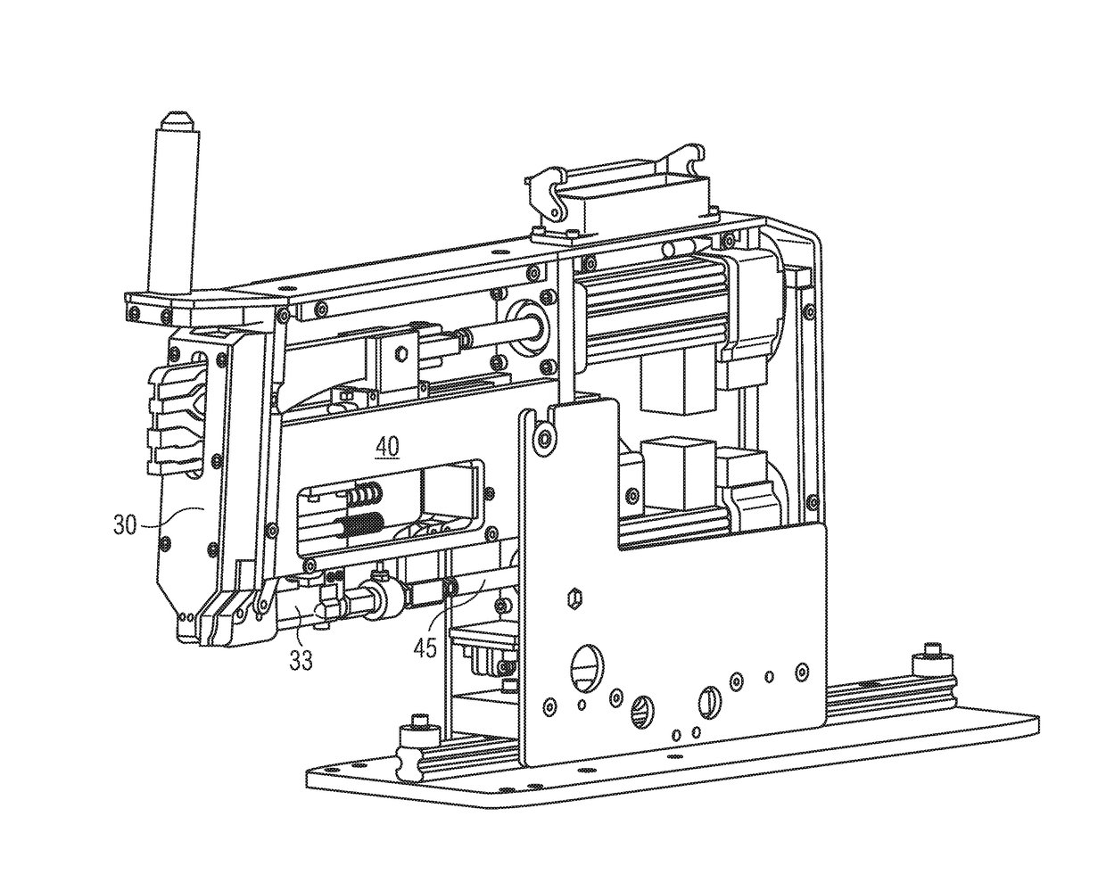
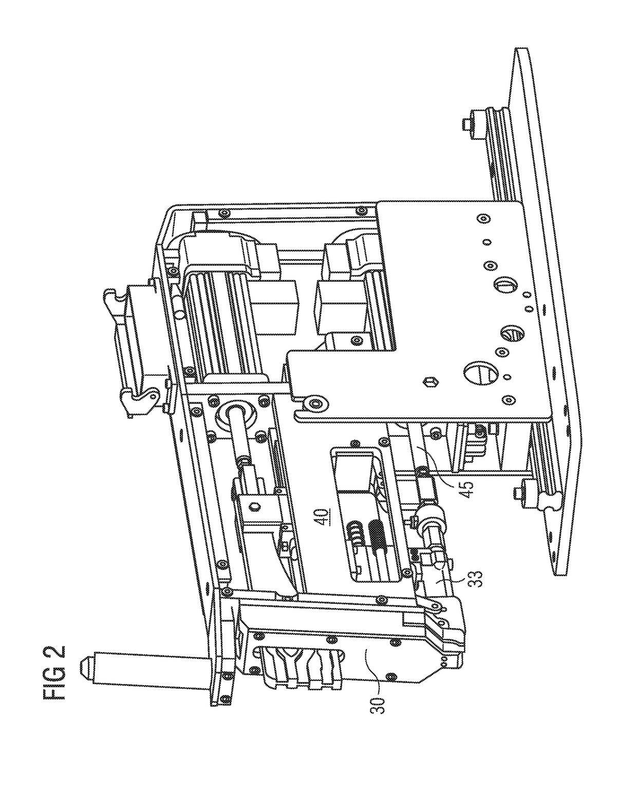
[0027]The tool shown in FIG. 2 includes a holding device for holding the tension clamp 19 and the object to be fastened (not shown) which is surrounded by the clamp, a tensioning device for tensioning the tension clamp 19 round the objec...


PUM

PropertyMeasurementUnit
Forceaaaaaaaaaa
Tensionaaaaaaaaaa

Abstract

A tension clamp (19) includes a band (20) surrounding an object to be fastened and a buckle (21) arranged on the inner band end portion (22) and surrounding the band (20), with the outer band end portion (23) extending through the buckle (21). A tool for mounting the tension clamp includes a holding device for holding the buckle (21) along with the band (20) surrounding the object to be fastened, a tensioning device for tensioning the band (20) round the object to be fastened by applying tension to the outer band end portion (23), a locking device (50) for locking the buckle (21) on dem band (20), and a severing device for cutting off excessive band length. The locking device (50) has plier jaws (54) adapted to be inserted into lateral windows (25) of the buckle (21) for deforming side edge portions (24) of the other band end portion (23).

Description

PRIOR ART[0001]For mounting an object such as an air bag material on a gas generator or an air bag on a mounting plate, tension clamps, such as known from U.S. Pat. No. 8,424,166 B2, are used which consist of a band and a buckle disposed on one end portion of the band.[0002]U.S. 2009 / 0114308 A1 discloses a tool by which such a tension clamp, which has been pre-assembled from a band and a buckle and placed on the object, is tensioned round the object, the buckle is subsequently locked on the band, and the excessive length of the outer band end is cut off. To do so, the object to be fastened including the tension clamp is placed in a holder, the outer band end is clamped between a tensioning roller and a pressure roller, and the tensioning roller is rotated. When a given band tension or a given rotation of the pressure roller is reached the band is locked to the buckle by being deformed within the buckle using a spring-loaded plunger. At the same time, the outer band end which project...

Claims


Application Information

Patent Timeline
IPC IPC(8): B65B13/30B25B25/00B65B13/02B65D63/08
CPCB65B13/30B65D63/08B65B13/02B25B25/005B21D39/031B65B13/027B65B13/305B25B25/00B65D63/04B65B13/18B65B13/185
Inventor SEELOS, ROBERTDE VITTORI, NELSONSTEINER, PETER
Owner OETIKER SCHWEIZ AG
Why Eureka
Try Eureka