System and Method for Controlling Multi-Zone Vapor Compression System

a vapor compression system and multi-zone technology, applied in the field of vapor compression systems, can solve the problems of significantly more memory for parameter storage, unpractical manual specification of optimization problems for every configuration,

Active Publication Date: 2017-12-07
MITSUBISHI ELECTRIC RES LAB INC
View PDF3 Cites 14 Cited by
  • Summary
  • Abstract
  • Description
  • Claims
  • Application Information

AI Technical Summary

Benefits of technology

[0008]It is an object of some embodiments of the invention to provide a system and a method for controlling operations of a multi-zone vapor compression system (MZ-VCS). It is another object of some embodiments of the invention to provide a system and method for controlling the vapor compression system predictively using a model of the system dynamics to determine and solve an optimization problem such that constraints on the operation of the MZ-VCS are enforced. It is another object of some embodiments to control the operation of a MZ-VCS where zones are permitted to become active or inactive. Further, it is an object of some embodiments that the controller can be modified online to adapt to the specific machine configuration, that is, the specific combination of heat exchangers that are active and inactive.

Problems solved by technology

Because deactivating a zone fundamentally changes the structure of the optimization problem, different optimization problems specific to every system configuration need to be specified, but manually specifying an optimization problem for every configuration is not practical for the large number of possible configurations.
Further, the sets of different controller parameters encoding the different optimization problems would all need to be available at runtime, requiring significantly more memory for parameter storage than is typically available for embedded hardware.

Method used


Image

  • System and Method for Controlling Multi-Zone Vapor Compression System
  • System and Method for Controlling Multi-Zone Vapor Compression System
  • System and Method for Controlling Multi-Zone Vapor Compression System

Examples


Embodiment Construction

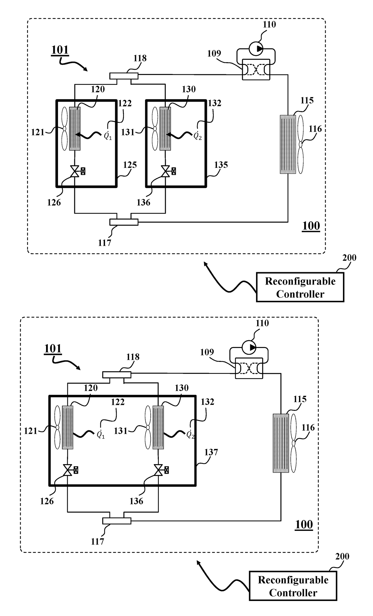
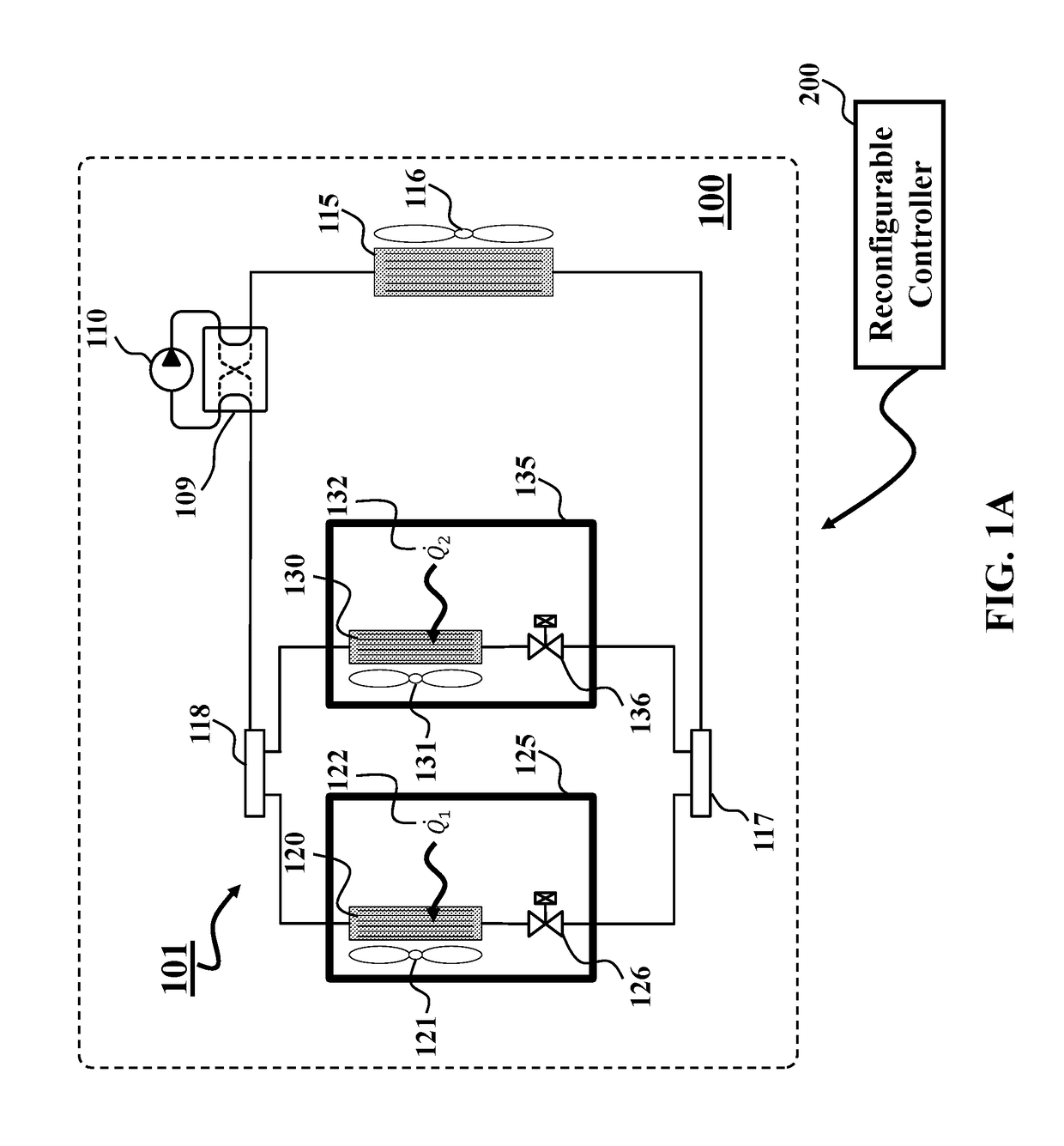
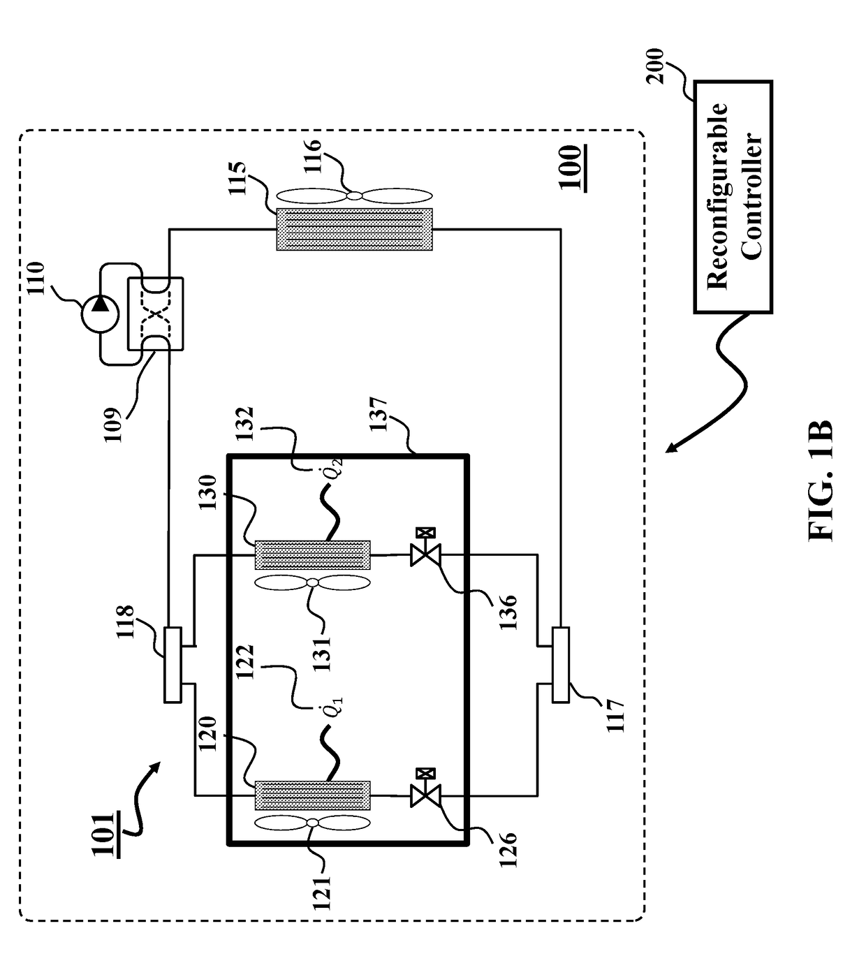
[0044]A multi-zone vapor compression system (MZ-VCS) of some embodiments of the invention includes an ability to deactivate one or more heat exchangers while the remaining heat exchangers continue to provide service. For instance, an occupant may anticipate that a zone in a space is unoccupied and can shut off the heat exchanger in order to reduce energy consumption by not conditioning the air in the occupied space. In this case, the decision to deactivate a zone and the corresponding heat exchanger is determined by a source external (the occupant) to the MZ-VCS controller.

[0045]Additionally or alternatively, in one embodiment, the MZ-VCS controller can determine that the local heating or cooling loads in a particular zone are lower than the minimum continuously available amount of heating or cooling provided by the heat exchanger and can automatically deactivate the heat exchanger. In this case, the MZ-VCS controller itself has determined that a particular zone is to be deactivated...


PUM


Abstract

A system controls a multi-zone vapor compression system (MZ-VCS). The system includes a controller to control a vapor compression cycle of the MZ-VCS using a set of control inputs determined by optimizing a cost function including a set of control parameters. The optimizing is subject to constraints, and wherein the cost function is optimized over a prediction horizon. The system also includes a memory to store an optimization function parameterized by a configuration of the MZ-VCS defining active or inactive modes of each heat exchanger, the optimization function modifies, according to a current configuration, values of the control parameters of the cost function determined for a full configuration that includes all heat exchangers in the active mode. The system also includes a processor to determine the current configuration of the MZ-VCS and to update the cost function by submitting the current configuration to the optimization function.

Description

FIELD OF THE INVENTION[0001]This invention relates to vapor compression systems, and more particularly to a system and a method for controlling a multiple-zone vapor compression system.BACKGROUND OF THE INVENTION[0002]Vapor compression systems (VCS) move thermal energy between a low temperature environment and a high temperature environment in order to perform cooling or heating operations so that the comfort of the occupants in an indoor space can be maintained or improved. For example, heat can be moved from an indoor space to an outdoor space in order to lower the indoor temperature or mitigate the effect of thermal energy infiltrating an indoor space in a cooling operation. Conversely, heat can be moved from an outdoor space to an indoor space in order to raise the indoor temperature or mitigate the effect of thermal energy exfiltration an indoor space in a heating operation.[0003]A multi-zone vapor compression system (MZ-VCS) includes at least a single compressor and single out...

Claims


Application Information

Patent Timeline
Patent Type & Authority Applications(United States)
IPC IPC(8): F25B13/00F25B49/02
CPCF25B13/00F25B2313/02331F25B49/02F24F11/30F24F2110/10F24F2140/60F24F11/64F25B2313/029
Inventor BURNS, DANIEL J.ZHOU, JUNQIANGDANIELSON, CLAUSDI CAIRANO, STEFANO
Owner MITSUBISHI ELECTRIC RES LAB INC
Why Eureka
Try Eureka