

Method and system for refined positioning via intersection of hyper zones
- Summary
- Abstract
- Description
- Claims
- Application Information
AI Technical Summary
Benefits of technology
Problems solved by technology
Method used
Image

Examples
first embodiment
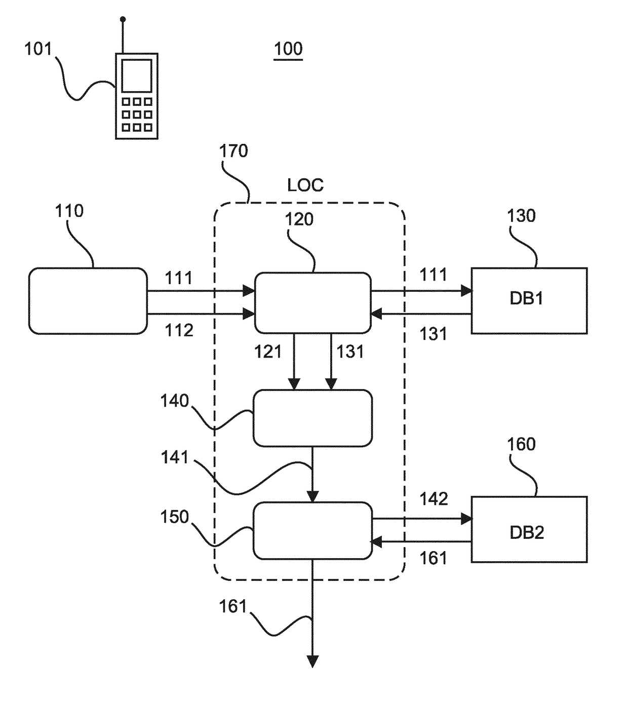
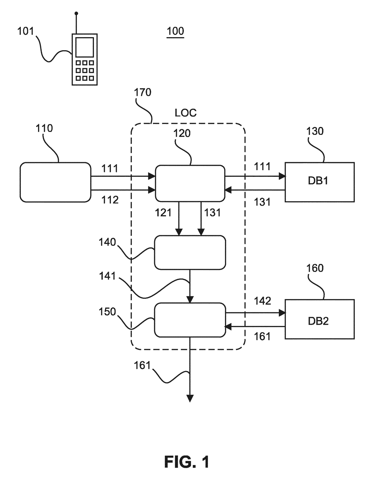
[0033]FIG. 1 shows a schematic block diagram of location system 100 with a measuring unit 110, an identification unit 120, a selection unit 140 and an intersection unit 150, and two databases (DB1, DB2) 130 and 160. The two databases may be implemented by respective look-up tables or memory regions of a single data storage device. The measuring unit 110 is adapted to select anchor nodes (not shown in FIG. 1) and to measure signal strengths between a radio unit 101 and the selected anchor nodes. The measuring unit 110 passes on anchor node identifiers 111 and corresponding signal strength values (e.g., RSSI values) 112 to the identification unit 120. The identification unit 120 is adapted to fetch from the first database 130 hyper-zone identifiers 131 of two anchor group types of hyper zones which correspond to the anchor node identifiers 111, and then to compute hyper-zone signal strength values 121 for the fetched anchor groups of hyper zones of each type. The hyper-zone signal st...
second embodiment
[0045]FIG. 7 shows a flow diagram of a zone-based location procedure according to a
[0046]In a first step 701 anchor nodes that are within range of a target radio unit with unknown location are selected, so that the signal strengths or qualities between the anchor nodes and the target radio unit can be measured. In a subsequent step 702, identifiers of the selected anchor nodes are used to measure the signal strengths or qualities between the target radio unit and the radio anchors. In step 703, the obtained anchor node identifiers and corresponding signal strengths or qualities are used to derive the related hyper zones of the anchor nodes and to compute for each hyper zone a group strength or quality (e.g., average strength or quality of the anchor nodes of the hyper zone). Then, in step 704, hyper zones of each type with the highest group strength are selected. Finally, in step 705, the intersection region of the selected hyper zones of each type is determined, e.g., based on a lo...
PUM
 Abstract
Description
Claims
Application Information