Flow uniformity of air-cooled battery packs

a battery pack and airflow technology, applied in battery/fuel cell control arrangement, secondary cell details, hybrid vehicles, etc., can solve the problems of significant air flow (and concomitant temperature) non-uniformity among individual battery cells, damage to cells, and impact on their operation, so as to achieve more equitable distribution of cooling fluid and increase pressure

Active Publication Date: 2016-09-20
GM GLOBAL TECH OPERATIONS LLC
View PDF2 Cites 0 Cited by
  • Summary
  • Abstract
  • Description
  • Claims
  • Application Information

AI Technical Summary

Benefits of technology

[0006]In accordance with a first aspect of the present invention, modification of the surface of an air flow plenum or manifold about a series of battery cells arranged in a stacked relationship as part of a larger battery assembly (such as the aforementioned battery module or battery pack) is disclosed. In order to increase the inlet pressure of the first few channels at each battery module as a way to improve the uniformity of the flow rate of the individual cooling channels, the beads or related undulations that are used to enhance plenum stiffness may be built into the plenum flow path in particular locations as a way to promote a more equitable distribution of cooling fluid pressures. For example, by aligning such undulations into the cross-sectional area of the inlet plenum with the first few cooling channels of each module along the air flow direction, the beads (which may be thought of as forming indents or recesses within the inlet plenum at the portion of the plenum that corresponds to first few cooling channels of each module) increase local cross sectional area which in turn, locally increases the pressure. As such, this localized increase in static pressure tends to promote greater air flow through the adjacent channels of the first few cells of each module.
[0007]In the present context, the bead is any addition to the wall of the duct to not only enhance duct stiffness, but also improve the uniformity of the flow rates of individual cooling channels. Accordingly, bends, indentations and other features that are formed in the plenum or related ducting can raise the moment of inertia (and hence, stiffness) of the ducting, while simultaneously creating a favorable local high pressure regime for the coolant channels that are adjacent the beads. The width of each bead may be made to be approximately the same as the distance between two of the corresponding adjacent channels; this has the effect of reducing the variation in cooling air flow rate among the effected cells or modules by approximately 50%. Significantly, in situations where the beads are already being used to increase the stiffness of the plenum, their repositioning adjacent particular locations as discussed herein incurs no additional weight or complexity penalties. In one particular configuration, each battery module section has two beads placed on a surface of the inlet plenum adjacent the edges of the first few channels of each module.
[0008]In the present context, the battery pack is considered to be a substantially complete assembly or system of components necessary for propulsion of the vehicle for which the pack was designed, while battery modules and individual battery cells and cell units are (as mentioned above) considered to be subcomponents of the overall system. Such modular construction allows for ease of replacement of damaged or worn battery cells and modules without having to repair or replace the entire pack. Furthermore, an assembly of components for a battery pack used for vehicular applications may include—in addition to numerous battery cells—housings, cooling plates, frames, trays, securing mechanisms and other equipment that, while not contributing to the production of electric power, form an important part of the overall battery system assembly nonetheless.
[0010]According to yet another aspect of the invention, an automobile propulsion system is disclosed. In the present context, the nature of the automobile will be understood to include all road-going vehicular platforms, including cars, trucks, motorcycles, buses or the like. The propulsion system includes a battery pack assembly made up of numerous battery cells arranged in modular format such that cooling channels are defined between adjacent the cells within each module, as well as between adjacent modules. The system further includes components configured to deliver cooling fluid (such as air) to the various cells and modules within the pack; such components include a plenum, conduit, manifold or related duct that is placed in fluid communication with channels that are formed between adjacent cells with each module, as well as between adjacent modules. In one form, this ducting delivers the cooling fluid in a substantially sequential manner along the flow axis (which generally coincides with the stacking axis mentioned elsewhere in this disclosure) to the battery cells, modules and corresponding cooling channels. Stiffness-enhancing beads are formed on a surface of the ducting, and are placed adjacent a forward portion of at least one of the modules. In this way, the increase in localized cross sectional area causes the portion of the cooling fluid that passes through the channels at the forward end of a particular module to experience a localized pressure increase, which in turn offsets the decrease in pressure at the forward end of a particular module caused by the large distance between the last channel of a fluidly upstream battery module and the first channel of an adjacent downstream module. In a like manner, such beads may also be placed in the portion of the duct that is axially between adjacent modules with the same increased pressure effects. As mentioned above, the strategic placement of these beads promotes a more equitable distribution of the cooling fluid between the various inter-module and intra-module cooling channels. Additional equipment may include an air storage and delivery system, a drivetrain and (if necessary) a separate internal combustion engine (ICE) to provide hybrid power.

Problems solved by technology

Left unchecked, this excess built-up heat may damage the cells and impact their operation.
While such an approach has the virtue of providing a relatively unimpeded air flow path to all of the cells that are contiguous with the plenum, the potential exists for significant air flow (and concomitant temperature) non-uniformity among the individual battery cells; much of this is due to uneven pressure drops between the channels formed between adjacent cells or cooling plates as the air goes from the inlet plenum of the battery pack to the outlet plenum.
This problem is particularly significant in situations where there is a large distance between the last channel of a fluidly upstream battery module and the first channel of an adjacent downstream module; where this distance is larger than the distance between adjacent channels within the same module, the resulting pressure difference is such that the driving force (and resulting flow) in and around the first channel of each battery module is significantly reduced relative to its more closely-aligned intra-module channels.

Method used


Image

  • Flow uniformity of air-cooled battery packs
  • Flow uniformity of air-cooled battery packs
  • Flow uniformity of air-cooled battery packs

Examples


Embodiment Construction

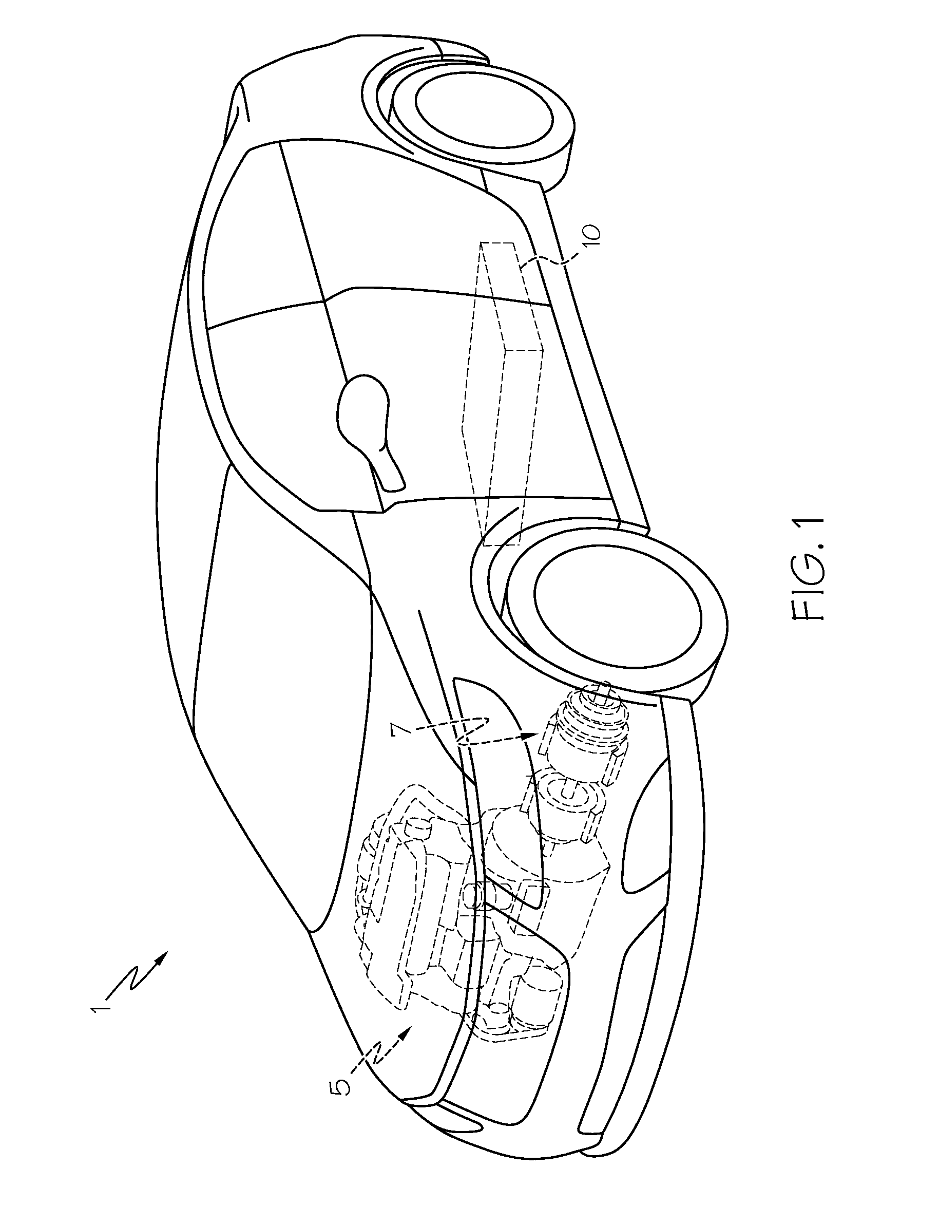
[0018]Referring first to FIG. 1, a vehicle 1 includes a hybrid propulsion system in the form of an electric power source made up of a conventional ICE 5 and a battery pack 10. Such a vehicle is known as a hybrid electric vehicle (HEV). It will be appreciated by those skilled in the art that vehicle 1 may not require an ICE 5, in such case, rather than being an HEV, it is an electric vehicle (EV); either form is within the scope of the present invention. An electric motor 7 may be coupled to one or both of the ICE 5 and battery pack 10 to provide traction to the wheels. Additional drivetrain components (none of which are shown) useful in providing propulsive power to one or more of the wheels and coupled to one or both of the battery pack 10 and ICE 5 are understood to include rotating shafts, axles, transmission, controllers or the like. While vehicle 1 is presently shown as a car, the applicability of the hybrid propulsion system to other such automotive forms (including trucks, bu...


PUM

PropertyMeasurementUnit
stiffnessaaaaaaaaaa
pressureaaaaaaaaaa
widthaaaaaaaaaa

Abstract

A battery pack and method of cooling a battery pack. In one form, the battery pack is an assembly made up of numerous battery cells arranged within numerous modules. Cooling channels that receive cooling fluid from a ducted supply are placed between adjacent cells or cooling plates within each of the modules. The ducted supply includes beads or related area-increasing undulations that are designed to improve both the stiffness of the ducting as well as the uniformity of the flow rates of individual cooling channels within each of the modules. In one form, the pressure-enhancing beads are placed in an inlet portion of the ducting that is adjacent a forward portion of one or more of the sequentially-encountered modules in order to promote a more equitable distribution of the cooling fluid between the various cooling channels within each of the modules.

Description

BACKGROUND OF THE INVENTION[0001]This invention relates generally to an improved air-cooled battery pack with a plurality of battery cells that are used to generate motive power for vehicular and related transportation applications, and more particularly to varying the air flow amongst the individual battery cells within a battery cell module or pack such that the flow depends on each battery's position within the respective module or pack.[0002]Various batteries, including lithium-ion, lead acid and nickel-metal hydride variants, may be configured to supplement or supplant conventional internal combustion engines (ICEs) for automotive and related transportation applications. The ability to passively store energy from stationary and portable sources, as well as from recaptured kinetic energy provided by the vehicle and its components, makes batteries (in general) and rechargeable batteries (in particular) ideal to serve as part of a propulsion system for cars, trucks, buses, motorcy...

Claims


Application Information

Patent Timeline
Patent Type & Authority Patents(United States)
IPC IPC(8): H01M10/02B60L11/18B60L3/00H01M10/36H01M10/625H01M10/60H01M10/65H01M10/613
CPCB60L11/1874B60L3/0046B60L2240/545H01M10/60H01M10/613H01M10/625H01M10/65Y02T10/7005Y10S903/907B60L58/26Y02E60/10Y02T10/70
Inventor SUN, HONGGUANGDIXON, REGAN P.
Owner GM GLOBAL TECH OPERATIONS LLC
Why Eureka
Try Eureka