
Dc-dc converter input voltage high-energy transient clamping topology

a converter and input voltage technology, applied in the direction of power electronics conversion efficiency emergency protective circuit arrangement, etc., can solve the problems of high energy consumption of input voltage transients, damage still often occurring, and damage to electrical components and systems, etc., to achieve high reliability, low cost, and tight performance specifications

Active Publication Date: 2017-12-07
SENSATA TECHNOLOGIES INC
View PDF5 Cites 0 Cited by
  • Summary
  • Abstract
  • Description
  • Claims
  • Application Information

AI Technical Summary

Benefits of technology

The patent describes a technology for controlling the voltage in a high-energy DC voltage bus application. The technology aims to achieve high reliability, tight performance specifications, and low cost. It uses a clamp circuit to protect the input voltage from damage and prevent unrecoverable hardware damage to other connected hardware. The technology also allows for DC output voltage regulation to the connected load during such transients. Overall, it offers a cost savings and improved performance, and can be scalable for any required rating.

Problems solved by technology

As is well-known, electrical components and systems can be subject to damage when subjected to excessive voltage and / or current transients.
Even though components and circuits typically have some design margin and various efforts have been made at dealing with transients, damage still often occurs.
One area with particular problems in dealing with transients is automotive applications and, in particular, electric vehicles.
Evolving battery-based system applications of DC-DC converters and other DC loads can include destructive input voltage transients having very high energy.
In effect, the entire surge rating of the power train may be applied to the potentially destructive input transient.

Method used


Image

  • Dc-dc converter input voltage high-energy transient clamping topology
  • Dc-dc converter input voltage high-energy transient clamping topology
  • Dc-dc converter input voltage high-energy transient clamping topology

Examples


Embodiment Construction

[0014]The subject technology overcomes many of the prior art problems associated with transients in electrical systems. The advantages, and other features of the systems and methods disclosed herein, will become more readily apparent to those having ordinary skill in the art from the following detailed description of certain preferred embodiments taken in conjunction with the drawings which set forth representative embodiments of the present invention and wherein like reference numerals identify similar structural elements. It is understood that references to the figures such as up, down, upward, downward, left, and right are with respect to the figures and not meant in a limiting sense.

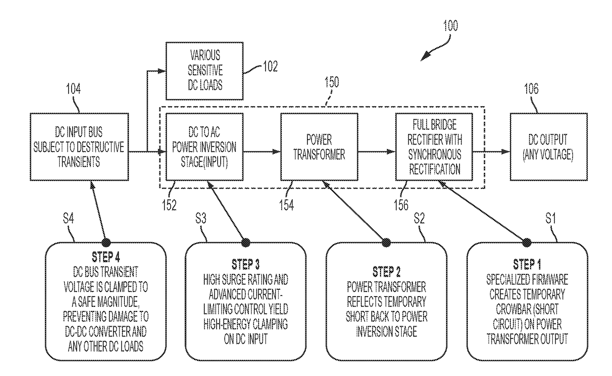
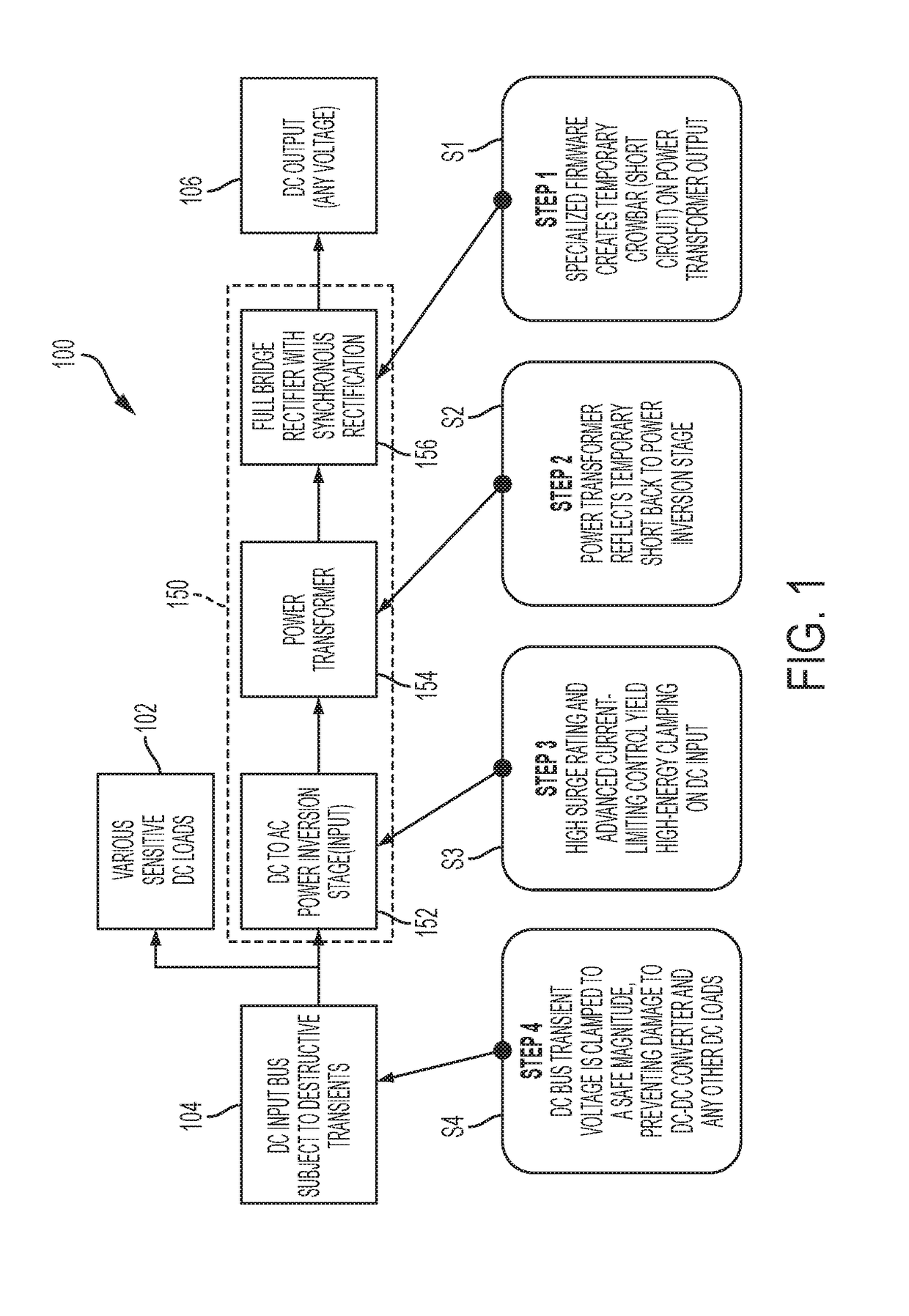
[0015]Referring now to FIG. 1, a block diagram representation of a clamping topology 100 in accordance with the subject disclosure is shown. The topology 100 protects various sensitive DC loads 102 being powered by a DC input bus 104, which may be subject to destructive transients. The topology 100 p...


PUM


Abstract

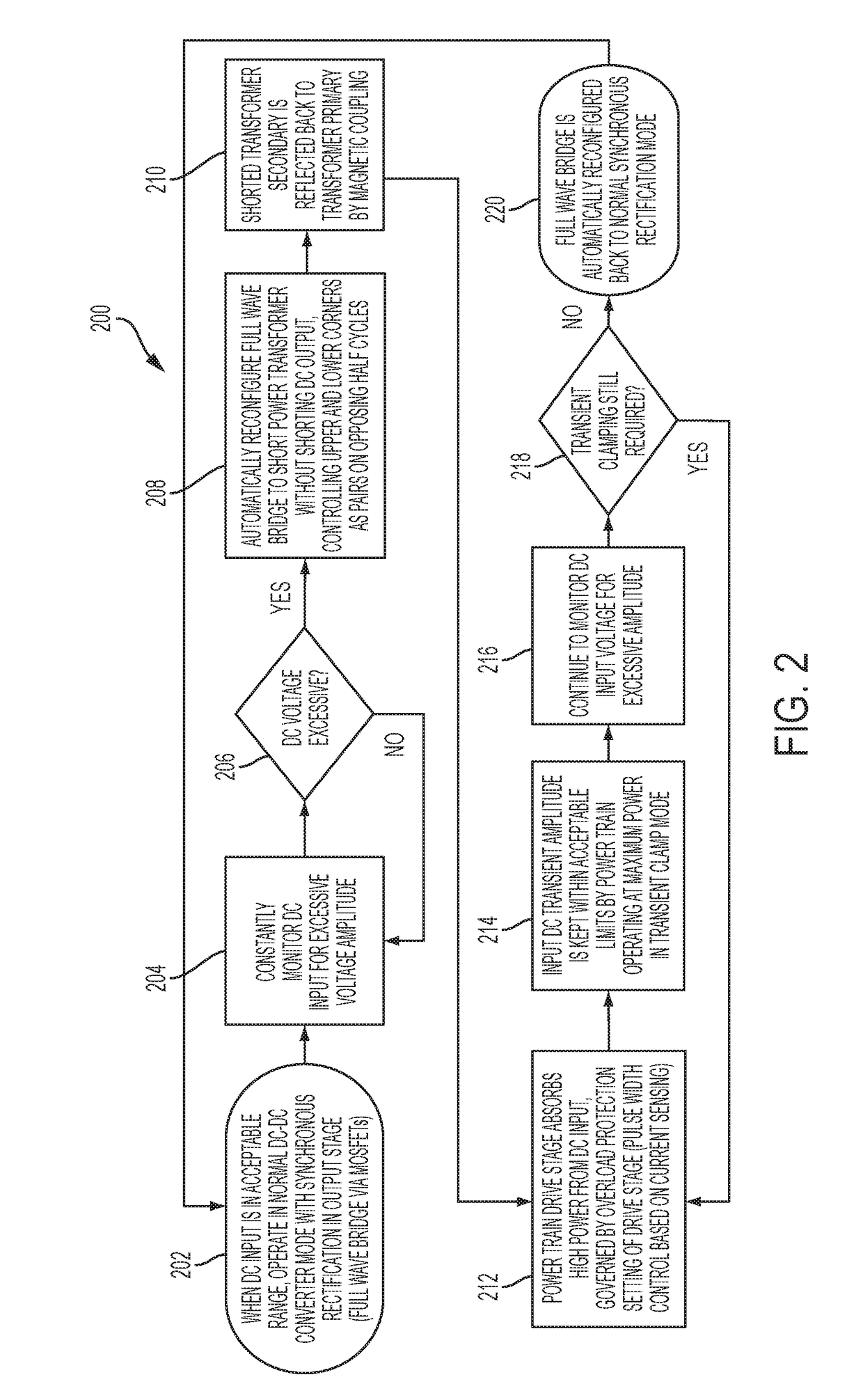
In electrical systems with DC-DC converters having synchronous rectification (SR) on the output stage, the input voltage can be monitored. When a potentially destructive transient occurs, the SR is rapidly turned on in a non-synchronous manner to “crowbar” the main power transformer. The resulting short circuit is reflected back to the DC input under current-limited pulse width modulation (PWM) control. In effect, the entire surge rating of the power train is applied to the potentially destructive input transient. The clamping capacity can be controlled accurately and is significantly more than what is available in prior art components and systems. When the input voltage is pulled down to safe levels, the clamp circuit disengages and the DC-DC converter returns to normal operation. DC output voltage regulation to the connected load is not maintained during this clamping event, but maintaining output voltage regulation during such destructive transients is not required.

Description

BACKGROUND OF THE INVENTION1. Field of the Invention[0001]The subject disclosure relates to methods and systems for clamping high-energy transients in applications such as battery-based systems.2. Background of the Related Art[0002]As is well-known, electrical components and systems can be subject to damage when subjected to excessive voltage and / or current transients. Even though components and circuits typically have some design margin and various efforts have been made at dealing with transients, damage still often occurs. One area with particular problems in dealing with transients is automotive applications and, in particular, electric vehicles. Evolving battery-based system applications of DC-DC converters and other DC loads can include destructive input voltage transients having very high energy. The traditional transient clamping techniques of metal oxide varistor (MOV), diode-based transient suppressors, and spark gaps provide protection that is limited.[0003]One example of...

Claims


Application Information

Patent Timeline
Patent Type & Authority Applications(United States)
IPC IPC(8): H02M1/44H02M3/22
CPCH02M3/22H02M1/44H02M1/32H02H9/041H02H3/023H02H7/1213H02M3/33592Y02B70/10H02M3/335
Inventor SOLDNER, KIRK RANDALLJOHNSON, GARY NEIL
Owner SENSATA TECHNOLOGIES INC
Learn More