Battery housing of a traction battery of a motor vehicle

a technology of traction battery and battery housing, which is applied in the direction of batteries, cell components, vehicle sub-unit features, etc., can solve the problems of damage to the battery module of the traction battery, accommodated in the battery housing, etc., and achieve the effect of effective protection of the battery modul

Active Publication Date: 2017-12-14
DR ING H C F PORSCHE AG
View PDF3 Cites 13 Cited by
  • Summary
  • Abstract
  • Description
  • Claims
  • Application Information

AI Technical Summary

Benefits of technology

[0005]Described herein is a battery housing of a traction battery of a motor vehicle that offers particularly effective protection of the battery modules in the event of a crash.
[0007]The battery housing is based on the concept of creating defined deformation spaces between the battery modules and the inner sides of the side walls of the battery housing and of providing deformation elements therein, which, in the event of a crash, can be deformed and, in the process, can absorb energy. It is therefore avoided in an advantageous manner that the battery modules themselves lie directly against the side walls of the battery housing. The side walls themselves are preferably designed as extruded profiles. The risk of damage to the battery modules in the event of a crash, in particular in a side impact, can be effectively reduced by the measures according to aspects of the invention. The battery housing can preferably be screwed to the underbody structure of the motor vehicle and can thereby be integrated in the underbody structure. As an alternative, it is also possible for the battery housing to be formed integrally with the underbody structure of the motor vehicle.
[0008]In a preferred embodiment, it is proposed that each of the receiving spaces comprises two transverse profiles which extend parallel to each other in the transverse direction of the motor vehicle and are spaced apart from each other in the longitudinal direction of the motor vehicle, wherein at least one of the transverse profiles is connected to one of the deformation elements. In other words, in this embodiment, two adjacent transverse profiles therefore each bound one of the receiving spaces. The transverse profiles serve here in particular to increase the mechanical stability of the battery housing. Owing to the fact that the deformation elements are connected to the transverse profiles, assemblies having heterogeneous rheological properties can be created since it is possible for the deformation elements to have different rheological properties than the transverse profiles. For example, the deformation elements can have a lower degree of rigidity than the transverse profiles. By adjustment of the rheological properties of the transverse profiles and of the deformation elements, the mechanical behavior of the battery housing in the event of a crash, in particular in a side impact, can be adapted in a specific manner. In the preferred embodiment, a transverse profile of the first and last receiving space in the longitudinal direction of the motor vehicle is in each case connected here to one of the deformation elements, whereas, in all of the other receiving spaces, the two transverse profiles are connected to one deformation element each.
[0015]For improved deformation behavior of the deformation elements, it is proposed, in a particularly preferred embodiment, that each of the deformation elements has two connecting portions which extend between the holding portion and / or the fastening portion and the supporting portion obliquely with respect to the plane of the supporting portion. The supporting portion and the two connecting portions which lead into the holding portion and / or into the fastening portion of the deformation element can in particular form an open triangular cross-sectional shape. The design of the deformation elements can be adapted here in a specific manner to the desired deformation behavior of the deformation elements.
[0016]In a particularly preferred embodiment, it can be provided that the deformation elements are designed as extruded profile parts. As a result, it is possible, for example, to create even more complex designs of the deformation elements, wherein, nevertheless, the tool costs for the production of the deformation element can be relatively low.

Problems solved by technology

In the event of a crash, in particular in a side impact, there is the problem that the battery modules of the traction battery that are accommodated within the battery housing may under some circumstances become damaged because of the high mechanical loads, and therefore, for example, electrolytic fluids may escape out of the battery modules.

Method used


Image

  • Battery housing of a traction battery of a motor vehicle
  • Battery housing of a traction battery of a motor vehicle
  • Battery housing of a traction battery of a motor vehicle

Examples


Embodiment Construction

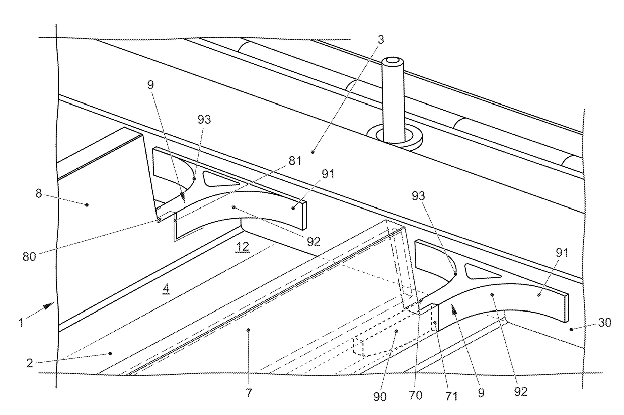
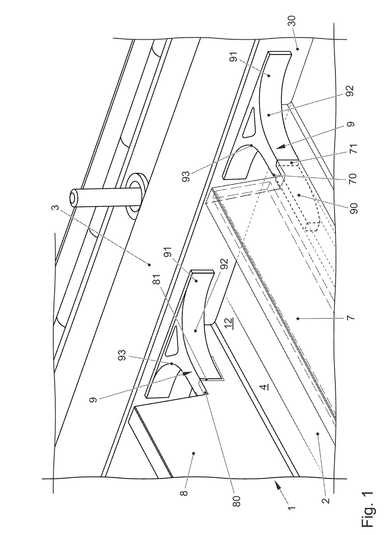
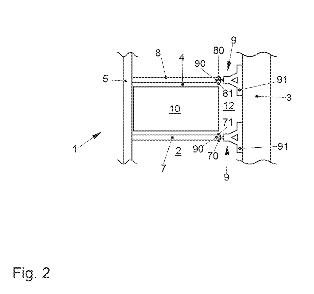
[0024]With reference to FIGS. 1 to 4, a battery housing 1 of a traction battery of a motor vehicle, said battery housing being designed according to a first exemplary embodiment of the present invention and within which a plurality of battery modules 10 of the traction battery can be accommodated, comprises a base plate 2 and two side walls 3 which extend parallel to each other in the longitudinal direction (x direction) of the motor vehicle and are spaced apart from each other in the transverse direction (y direction) of the motor vehicle. Only one of said two side walls 3, which can be designed, for example, as extruded profiles, can be seen in the figures. This is the side wall 3 which is provided on a right side of the vehicle in the forward direction of travel of the motor vehicle, which has been symbolized in FIG. 2 by an arrow tip of the x axis of the Cartesian system of co-ordinates.

[0025]The battery housing 1 has a number of receiving spaces 4, within each of which at least...


PUM


Abstract

A battery housing of a motor vehicle traction battery includes at least one base plate, and two side walls which extend parallel to each other in the longitudinal direction of the motor vehicle and are spaced apart from each other in the transverse direction of the motor vehicle. Formed between the side walls is a number of receiving spaces, within each of which at least one battery module of the traction battery of the motor vehicle is accommodated. A plurality of deformation elements which are spaced apart from one another in the longitudinal direction of the motor vehicle are attached to the inner sides of the side walls. The battery modules are arranged in the receiving spaces in such a manner that, in the region of the deformation elements, lateral deformation spaces are formed between the battery modules and the side walls.

Description

CROSS-REFERENCE TO RELATED APPLICATIONS[0001]This application claims priority to German Patent Application No. 102016110787.5, filed Jun. 13, 2016, the content of such application being incorporated by reference herein in its entirety.FIELD OF THE INVENTION[0002]The present invention relates to a battery housing of a traction battery of a motor vehicle, the traction battery being integrated in an underbody structure of the motor vehicle, comprising at least one base plate, and two side walls which extend parallel to each other in the longitudinal direction of the motor vehicle and are spaced apart from each other in the transverse direction of the motor vehicle, wherein formed between the side walls is a number of receiving spaces, within each of which at least one battery module of the traction battery of the motor vehicle is accommodated.BACKGROUND OF THE INVENTION[0003]Motor vehicles which comprise an electric engine as the driving device instead of an internal combustion engine ...

Claims


Application Information

Patent Timeline
Patent Type & Authority Applications(United States)
IPC IPC(8): B60K1/04B62D21/15B62D27/02B62D25/20
CPCB60K1/04B62D21/157B60Y2306/01B62D27/023B60K2001/0438B62D25/2036B60K2001/0405H01M50/24H01M50/20Y02T10/70Y02E60/10B60L50/64H01M2220/20H01M50/249
Inventor BRAUSSE, STEPHANHEINZ, PHILIPPRACITI, MICHAEL
Owner DR ING H C F PORSCHE AG
Why Eureka
Try Eureka