Identifying camera position of a UAV in flight utilizing real time kinematic satellite navigation

Active Publication Date: 2017-12-14
SKYCATCH
View PDF5 Cites 23 Cited by
  • Summary
  • Abstract
  • Description
  • Claims
  • Application Information

AI Technical Summary

Benefits of technology

[0007]Embodiments of the present disclosure provide benefits and/or solve one or more of the foregoing or other problems in the art with systems and methods for identifying a precise location of a camera affixed to a UAV in flight. In particular, in one or more embodiments, the disclosed systems and methods utilize real time kinematic (“RTK”) techniques to identify a precise position of a camera affixed to a UAV at a time when the camera captures a digital aerial image. For instance, in one or more embodiments, the disclosed systems and methods analyze a carrier signal transmitted from a number of satellites to identify a number of wave lengths between a GPS receiver of the UAV and each of the satelli

Problems solved by technology

Although such conventional flight systems allow users to utilize a UAV to generate three-dimensional models of a site, they also have a number of problems.
For example, it is often time-consuming and expensive to place and/or identify known survey ground control points in relation to a site.
Indeed, in implementations that repeatedly perform flight missions over a particular site, the amount of time and effort required to repeatedly place, measure, and maintain survey ground control points can significantly increase the cost of utilizing a UAV to capture digital aerial images and generate a three-dimensional model.
Furthermore, placing, measuring, and maintaining survey ground control points introduces a significant risk of human error.
Although these conventional GPS flight systems can id

Method used


Image

  • Identifying camera position of a UAV in flight utilizing real time kinematic satellite navigation
  • Identifying camera position of a UAV in flight utilizing real time kinematic satellite navigation
  • Identifying camera position of a UAV in flight utilizing real time kinematic satellite navigation

Examples


Embodiment Construction

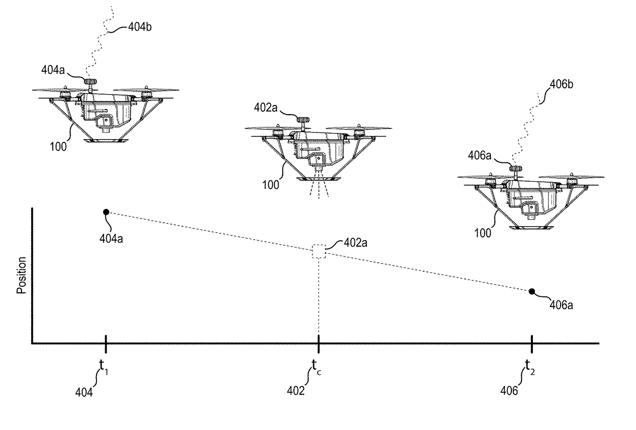
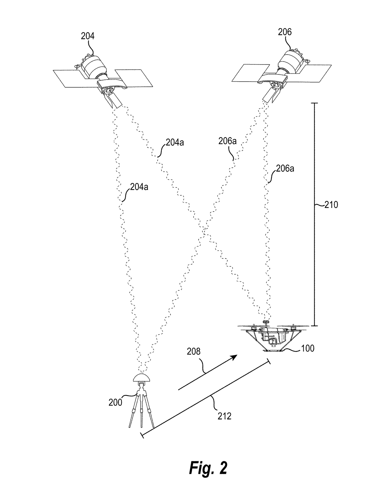
[0025]The present disclosure includes various embodiments and features of a digital unmanned aerial vehicle (“UAV”) position system and corresponding processes that assist in determining a precise position of a camera affixed to a UAV during a flight mission. In particular, in one or more embodiments the digital UAV position system determines a position of a camera affixed to a UAV at a time when the camera captures a digital aerial image. Specifically, in one or more embodiments, the digital UAV position system determines positions of a UAV based on the number of wavelengths in a carrier signal transmitted between a number of satellites and the UAV based on RTK correction data from one or more reference stations. Specifically, the digital UAV position system uses RTK data from the RTK reference station to solve for the integer number of wavelengths from the UAV's GPS antenna to each of the number of satellites. The digital UAV position system also determines precise times associate...


PUM


Abstract

Systems and methods are disclosed for determining a position of a camera affixed to a UAV in flight when the camera captures a digital aerial image. In particular, in one or more embodiments, the disclosed systems and methods utilize real time kinematic satellite navigation techniques to identify a position of a UAV. Moreover, the disclosed systems and methods precisely determine the time that a camera captures a digital aerial image together with an attitude of the UAV at the time of capture to calculate a location of a camera at the time of capture. In one or more embodiments, the disclosed systems and methods can utilize the determined position of the camera together with the captured digital aerial image to generate a three-dimensional representation of a site.

Description

BACKGROUND[0001]Individuals and businesses increasingly utilize UAVs to perform a variety of flight missions or tasks. Indeed, because of the reduced cost of UAVs relative to chartering manned aerial vehicles, businesses and individuals can engage in a variety of flight activities that were traditionally cost-prohibitive. For example, it is becoming increasingly common to utilize UAVs to perform flight missions for capturing digital aerial images of a site in construction, land management, mining, or other applications.[0002]In particular, some conventional flight systems utilize UAVs to generate three-dimensional models of a site. For example, some conventional digital image systems capture a plurality of digital aerial images of a site with a plurality of survey ground control points and then generate a three-dimensional model utilizing the digital aerial images and the known location of the survey ground control points. In particular, such conventional systems utilize survey grou...

Claims


Application Information

Patent Timeline
IPC IPC(8): B64C39/02H04N5/232G06K9/00G05D1/00G05D1/08G06V20/13G06V20/17
CPCB64C39/024G06K9/0063H04N5/232B64C2201/024G05D1/0808B64C2201/127B64C2201/145G05D1/0094G05D1/0858B64C29/0033G08G5/0069G06T17/05G08G5/0086G08G5/0021G06V20/13G06V20/17B64U2101/30B64U2201/104B64U10/10
Inventor CHEN, DAVIDTWITTY, COLLEEN KELLYSCHANFELDT, BLAINEJOHNSON, JAMES J.FEDERICO, JACOB
Owner SKYCATCH
Why Eureka
Try Eureka