Method and system for maximizing production of a well with a gas assisted plunger lift

Active Publication Date: 2017-12-14
ABB (SCHWEIZ) AG
View PDF9 Cites 10 Cited by
  • Summary
  • Abstract
  • Description
  • Claims
  • Application Information

AI Technical Summary

Benefits of technology

[0011]The invention provides a method and system for maximizing production of a well such as a hydrocarbon or fossil fuel well. The well comprises a casing connected to a gas injection line, a tubing connected to a sales line, a production valve for controlling supply to the sales l

Problems solved by technology

However, the abovementioned methods are targeted towards plunger lift; and are incomplete and/or inapplicable for the GAPL operation as they do not consider the effect of injection gas.
While methods of injection of lift gas, optimization of gas lift production, gas lift control are generally known, these are not directly relevant to GAPL.
Thus adaptive or model-based control ideas from gas lift are not applicable to GAPL.
The opera

Method used


Image

  • Method and system for maximizing production of a well with a gas assisted plunger lift
  • Method and system for maximizing production of a well with a gas assisted plunger lift
  • Method and system for maximizing production of a well with a gas assisted plunger lift

Examples


Embodiment Construction

[0027]The invention relates to maximizing production of a well such as a hydrocarbon or a fossil fuel well.

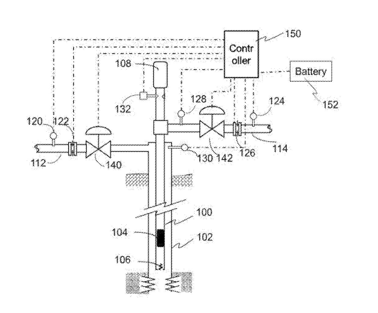
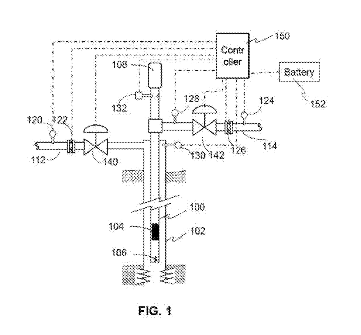
[0028]FIG. 1 illustrates a well with a Gas Assisted Plunger Lift (GAPL). The well has an outer tube called casing (102), which is connected to an injection line (112); and an inner tube called tubing (100), which is connected to a sales line (114). The well also has a production valve (142) that can be opened or closed to allow the well to flow or shut-in; and an injection valve (140) that can be opened at specified percent to allow the gas to flow from injection to casing.

[0029]In addition, a plunger (104) is provided that can move up or down the tubing. When the production valve is opened, the plunger is intended to eventually come to rest in a catcher / lubricator (108) located at the well-head. When the production valve is closed, the plunger falls and eventually comes to rest at the bottom seat (106).

[0030]A controller (150) is provided to collect measurements, determine con...


PUM


Abstract

The invention provides a method and system for maximizing production of a well with a gas assisted plunger lift. The method comprises obtaining a plurality of measurements associated with operation of the well from sensors associated with various components of the well. The method further comprises determining set points for operation of the production valve and the injection valve based on one or more of the plurality of measurements. The set points may be determined by the controller or by a SCADA system. Optionally, one or more of the set points may be modified according to a comparison of current and optimal values of plunger velocity and gas and liquid production. In addition, the method comprises coordinating the operation of the production valve and the injection valve is coordinated based on the set points and the stage in operation cycle by the controller.

Description


Claims


Application Information

Patent Timeline
Owner ABB (SCHWEIZ) AG
Why Eureka
Try Eureka