System and method for mitigating cylinder deactivation degradation

a technology of cylinder deactivation and system, applied in the direction of machines/engines, output power, electric control, etc., can solve the problems of reducing engine emissions, reducing engine degradation, and reducing engine degradation, so as to reduce the possibility of valve or valve operator degradation

Active Publication Date: 2017-12-14
FORD GLOBAL TECH LLC
View PDF2 Cites 30 Cited by
  • Summary
  • Abstract
  • Description
  • Claims
  • Application Information

AI Technical Summary

Benefits of technology

[0003]An internal combustion engine may be fitted with deactivating valve operators. The deactivating valve operators may allow selected cylinders to be activated and deactivated based on engine operating conditions. Engine cylinders are typically deactivated at lower engine speeds and loads. Engine cylinders are typically activated at higher engine speeds and loads. The deactivating valve operator may leave intake valves and exhaust valves in a closed state when cylinders are deactivated. The valve operators may lift and release intake and exhaust valves when the cylinders are activated. However, if an intake valve operator of a cylinder remains in a deactivated state after it is requested to operate, fresh air flow into the cylinder may not occur while at the same time fuel may be injected to the cylinder. As a result, fuel in the cylinder may not combust and it may be ejected to the engine exhaust system. Therefore, it may be desirable to provide a way to mitigate the possibility of valve or valve operator degradation.
[0005]By deactivating all poppet valves of a cylinder in response to an indication that a poppet valve of the cylinder is not operating (e.g., opening and closing during an engine cycle), it may be possible to provide the technical result of reducing the possibility of engine degradation. Further, fuel flow may be ceased to the cylinder. In this way, flow through the cylinder and fuel delivery to the cylinder may be inhibited so that excess fuel is not ejected to the exhaust system. Further, fresh air is not passed through the cylinder to the exhaust system where it may upset a balance of oxygen in a catalyst in the exhaust system.
[0006]The present description may provide several advantages. In particular, the approach may reduce the possibility of engine degradation. Further, the approach may reduce engine emissions. Further still, the approach may conserve fuel.

Problems solved by technology

Further, fresh air is not passed through the cylinder to the exhaust system where it may upset a balance of oxygen in a catalyst in the exhaust system.
In particular, the approach may reduce the possibility of engine degradation.
Further, the approach may reduce engine emissions.

Method used


Image

  • System and method for mitigating cylinder deactivation degradation
  • System and method for mitigating cylinder deactivation degradation
  • System and method for mitigating cylinder deactivation degradation

Examples


Embodiment Construction

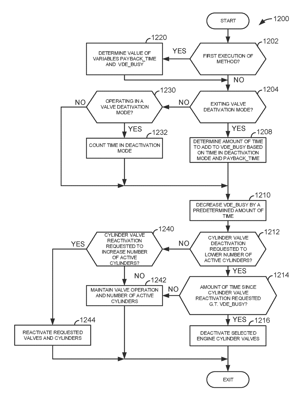
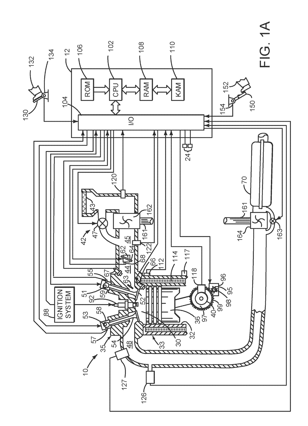
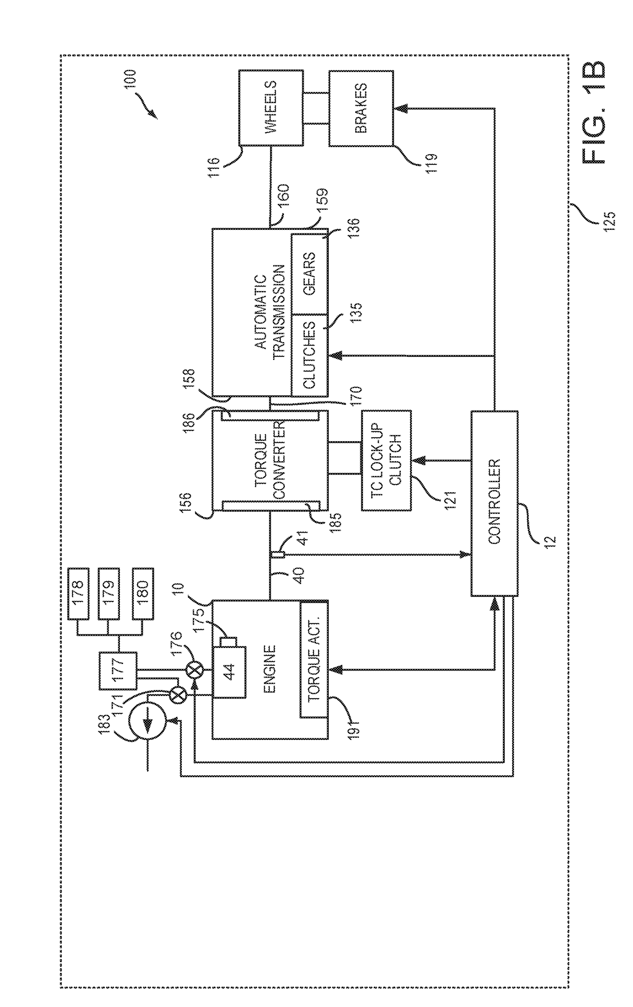
[0060]The present description is related to systems and methods for selectively activating and deactivating cylinders and cylinder valves of an internal combustion engine. The engine may be configured and operate as is shown in FIGS. 1A-6D. Various methods and prophetic operating sequences for an engine that includes deactivating valves are shown in FIGS. 7-42. The different methods may operate cooperatively and with the systems shown in FIGS. 1A-6D.

[0061]Referring to FIG. 1A, internal combustion engine 10, comprising a plurality of cylinders, one cylinder of which is shown in FIG. 1A, is controlled by electronic engine controller 12. Engine 10 is comprised of cylinder head casting 35 and block 33, which include combustion chamber 30 and cylinder walls 32. Piston 36 is positioned therein and reciprocates via a connection to crankshaft 40. Flywheel 97 and ring gear 99 are coupled to crankshaft 40. Starter 96 (e.g., low voltage (operated with less than 30 volts) electric machine) incl...


PUM


Abstract

Systems and methods for operating an engine with deactivating and non-deactivating valves are presented. In one example, valves of a cylinder are deactivated in a closed state in response to an indication of degradation of a valve of the cylinder. Further, fuel flow to the cylinder may be stopped via ceasing to inject fuel to the cylinder.

Description

CROSS REFERENCE TO RELATED APPLICATION[0001]The present application claims priority to U.S. Provisional Patent Application Ser. No. 62 / 347,826, filed on Jun. 9, 2016. The entire contents of the above-referenced application are hereby incorporated by reference in its entirety for all purposes.FIELD[0002]The present description relates to systems and methods for selectively deactivating and activating one or more cylinders of an internal combustion engine. The systems and methods may be applied to engines that operate poppet valves to control flow into and out of engine cylinders.BACKGROUND AND SUMMARY[0003]An internal combustion engine may be fitted with deactivating valve operators. The deactivating valve operators may allow selected cylinders to be activated and deactivated based on engine operating conditions. Engine cylinders are typically deactivated at lower engine speeds and loads. Engine cylinders are typically activated at higher engine speeds and loads. The deactivating val...

Claims


Application Information

Patent Timeline
Patent Type & Authority Applications(United States)
IPC IPC(8): F02D41/00F02D17/02F01L13/00F02D41/26F02D41/30
CPCF02D41/0087F02D17/02F01L2013/001F02D41/26F01L13/0005F02D41/3005F02D41/123F02D41/22F01L1/181F02D13/04F02D13/06F02D41/0007F01L2001/0476F01L2001/0535F01L2001/0537F01L2001/186F01L2250/02F01L2250/04F01L2800/00F01L2810/02F02D2041/0012F01L2305/00Y02T10/12
Inventor ROLLINGER, JOHN ERICWILLARD, KARENDOERING, JEFFREY ALLENGRANT, ROBERT MICHAEL
Owner FORD GLOBAL TECH LLC
Why Eureka
Try Eureka