Introduced in a System for Connecting Refrigerant Fluid Discharge Tubes to Cylinder Caps of Hermetic Compressors, and Corresponding Process of Performing Thereof

a technology of refrigerant fluid and cylinder caps, which is applied in the direction of liquid fuel engines, positive displacement liquid engines, lighting and heating apparatus, etc., can solve the problems of compromising the entire operation of the cooling system, affecting the sealing conditions, and affecting the performance of the compressor, etc., to achieve the effect of convenient, quick and economical way, and optimal sealing conditions

Active Publication Date: 2017-12-14
EMBRACO IND DE COMPRESSORES E SOLUCOES EM REFRIGERACAO LTDA
View PDF8 Cites 1 Cited by
  • Summary
  • Abstract
  • Description
  • Claims
  • Application Information

AI Technical Summary

Benefits of technology

[0009]It is a further objective of the present invention to provide a system for connecting discharge tubes which aids in reducing the loss of load which, in similar known systems, was a consequence of the obstruction of the gas path by the screws or cap fixing elements, wherein the minimization of said loss of load results in a significant increase in efficiency of the compressor.
[0012]The present invention also aims to disclose a process of performing connection between the discharge tube and the compression cylinder cap, which provides optimal sealing conditions in a practical, quick and economical way.SUMMARY OF THE INVENTION

Problems solved by technology

However, it occurs that the thread form in the inner surface of the hole (101) of the block (100) ends up demanding more complex production processes which significantly increase the final cost of the piece.
Furthermore, the sealing of said connection—which is made only by interference, without the use of any additional sealing means—is totally dependent on the mechanical changes of said components, since it is only promoted by the expansion of the connecting member (120) as a consequence of the insertion of the discharge tube (110); however, it is known that dimensional variations occur during the processes for producing the components, so that there are risks that incidental variations may interfere with the proper sealing of the connection—which could compromise the entire operation of the cooling system and cause various inconveniences.
In view of the drawbacks above, it is noted that the present state of the art lacks practical, efficient and economical solutions to promote coupling between a discharge tube and the cylinder cap of a hermetic compressor.

Method used


Image

  • Introduced in a System for Connecting Refrigerant Fluid Discharge Tubes to Cylinder Caps of Hermetic Compressors, and Corresponding Process of Performing Thereof
  • Introduced in a System for Connecting Refrigerant Fluid Discharge Tubes to Cylinder Caps of Hermetic Compressors, and Corresponding Process of Performing Thereof
  • Introduced in a System for Connecting Refrigerant Fluid Discharge Tubes to Cylinder Caps of Hermetic Compressors, and Corresponding Process of Performing Thereof

Examples


Embodiment Construction

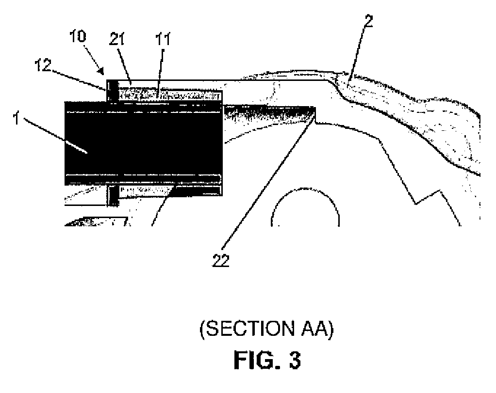
[0028]The subject matter of the present invention will be more fully described and explained on the basis of the accompanying drawings, which are of a merely exemplary and non-limiting character, since adaptations and modifications may be performed without, thereby, escaping from the claimed scope of protection.

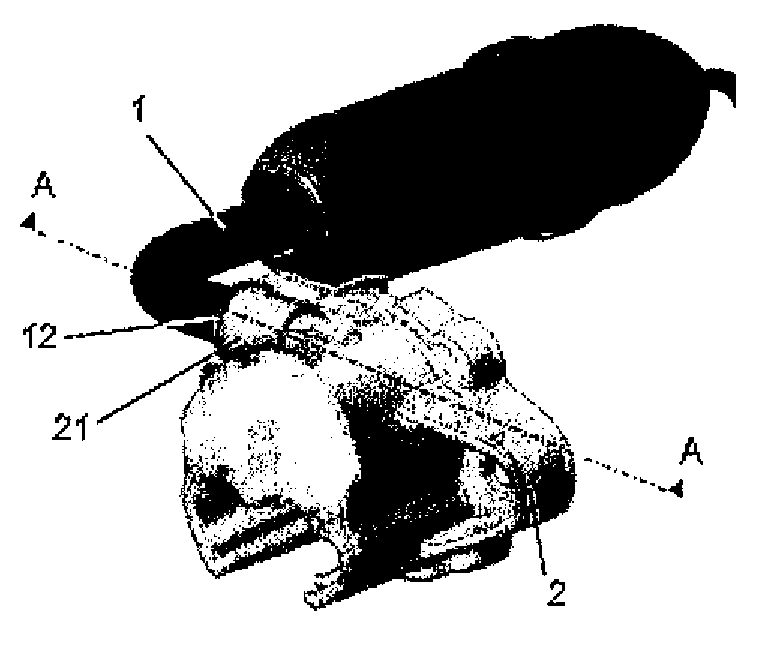
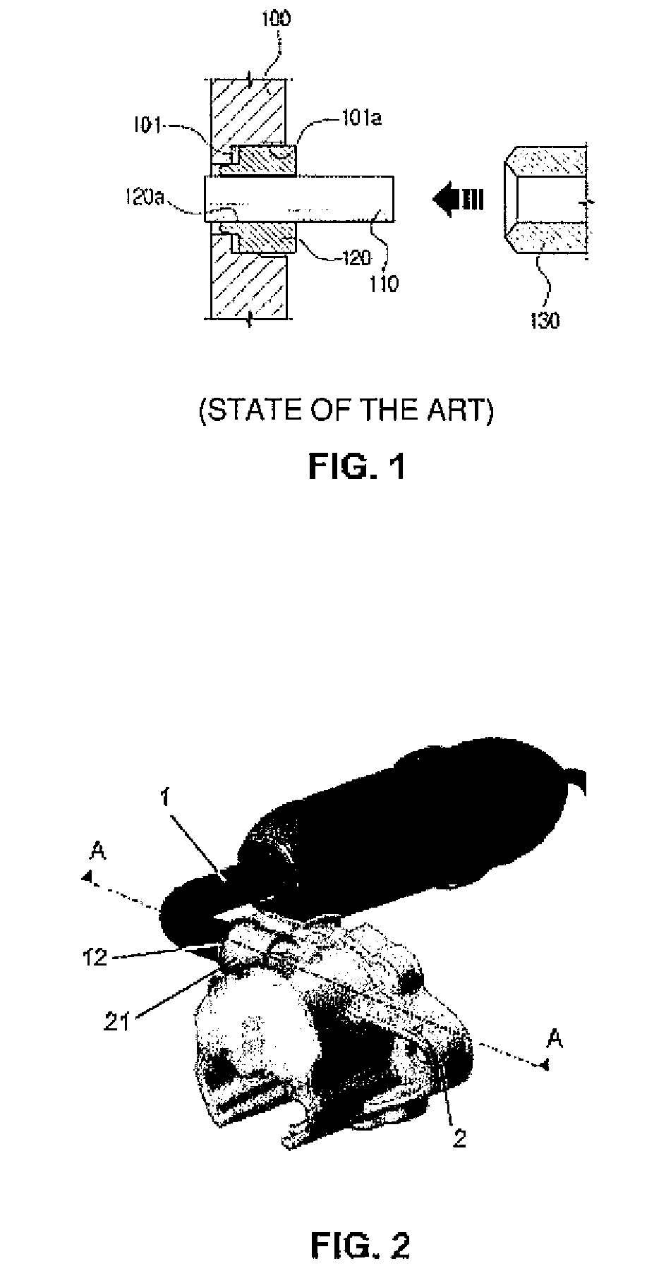
[0029]The present invention relates to a connecting device (10) which can be best observed by the cross section of the attached FIG. 3, in which it is performed the connection between a discharge tube (1) (produced in copper-covered steel or the like) and a cylinder cap (2) of a hermetic compressor for cooling system.

[0030]According to a preferred embodiment of the present invention, the connecting device (10) comprises a substantially cylindrical or tubular body (11) provided, at one of its ends, with a perimeter flap (12) which acts as an auxiliary element for the assembly of said connecting device (10) in the hole, duct or channel (21) of the cylinder cap (2). Preferably, ...


PUM

PropertyMeasurementUnit
pressureaaaaaaaaaa
mechanicalaaaaaaaaaa
thermal propertiesaaaaaaaaaa

Abstract

The present invention belongs to the technological field of compressors for cooling systems and, according to a preferred embodiment of the present invention, the connecting device a substantially cylindrical or tubular body provided, at one of its ends, with an outer perimetral projection and co-operative with a duct or channel of a cylinder cap, wherein, preferably, the device will be produced with steel, aluminum alloy, or other metal alloy with similar structural and thermal properties, mainly due to the stresses it may suffer during use and to be able to absorb the tolerance variations and to have a resilience capable of providing resistance at the time the connection undergoes mechanical stresses of performance—especially torsion.

Description

FIELD OF THE INVENTION[0001]The present invention relates to an improvement introduced in a system for connecting discharge tubes of hermetic compressors, more precisely to allow coupling between the refrigerant gas discharge tube and the cylinder cap of the compressor in a simpler, more practical, more efficient and more economical way than that achieved with the use of the like known in the present state of the art.BACKGROUND OF THE INVENTION[0002]As is well known, compressors are apparatus widely used in cooling systems, more precisely to promote continuous circulation of the refrigerant fluid in a cycle. For this purpose they comprise, inside a hermetically sealed housing, a mechanical assemblage comprising a block containing a cylindrical cavity in which a piston moves, wherein said cylinder is closed by a cap in which is located a discharge valve through which the refrigerant fluid with high pressure due to the actuation of the piston is expelled to continue its course in the ...

Claims


Application Information

Patent Timeline
Patent Type & Authority Applications(United States)
IPC IPC(8): F04B39/12F25B31/00F04B39/00F04B39/02F04C29/06
CPCF04B39/123F25B31/00F04B39/125F04C29/068F04B39/0055F04B39/023F04B2205/09F04B39/126F04B39/14B21D39/06B21D39/046
Inventor DE ANDRADE, DANIEL LACERDAARAUJO, GERSONESPINDOLA, GUILHERMEDOMINONI, JR., ADINOR
Owner EMBRACO IND DE COMPRESSORES E SOLUCOES EM REFRIGERACAO LTDA
Why Eureka
Try Eureka