Semiconductor device

a technology of semiconductors and devices, applied in the direction of semiconductor devices, basic electric elements, electrical equipment, etc., can solve the problems of low current density of power mosfets and difficulty in large-scale adaption

Active Publication Date: 2017-12-21
FUJI ELECTRIC CO LTD
View PDF7 Cites 5 Cited by
  • Summary
  • Abstract
  • Description
  • Claims
  • Application Information

AI Technical Summary

Benefits of technology

[0013]According to one aspect of the invention, a semiconductor device includes a semiconductor substrate of a first conductivity type and including a wide bandgap semiconductor having a bandgap wider than that of silicon; a first semiconductor layer of the first conductivity type provided on a front surface of the semiconductor substrate, the first semiconductor layer including the wide bandgap semiconductor and having an impurity concentration lower than that of the semiconductor substrate, the first semiconductor layer having a first side and a second side; a second semiconductor layer of a second conductivity type provided on the first side of the first semiconductor layer opposite the second side facing the semiconductor substrate, the semiconductor layer including the wide bandgap semiconductor and having a first side and a second side; a third semiconductor layer of the first conductivity type provided on the first side of the second semiconductor layer opposite the second side facing the semiconductor substrate, the third semiconductor layer including the wide bandgap semiconductor; a second-conductivity-type semiconductor region provided selectively in the third semiconductor layer, penetrating the third semiconductor layer in a depth direction and reaching the second semiconductor layer, the second-conductivity-type semiconductor region having an impurity concentration higher than that of the second semiconductor layer; a trench provided penetrating the third semiconductor layer and the second semiconductor layer, reaching the first semiconductor layer; a gate electrode provided in the trench via a gate insulating film; a first electrode provided in contact with the third semiconductor layer and the second-conductivity-type semiconductor region; and a second electrode provided in contact with a rear surface of the semiconductor substrate. A width between the trench and an adjacent trench and a depth of the trench are less than a minimum dimension achieving a predetermined current capacity material limit of silicon. The semiconductor device has a breakdown voltage of 1200V or higher.

Problems solved by technology

On the other hand, power MOSFETs have low current density compared to bipolar transistors and IGBTs, and are difficult to adapt for large current but can be switched at high speeds up to about several MHz.

Method used


Image

  • Semiconductor device
  • Semiconductor device
  • Semiconductor device

Examples


Embodiment Construction

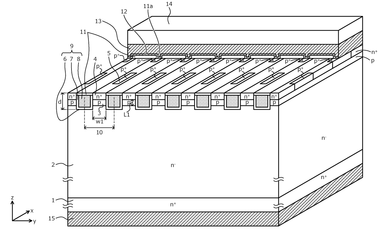
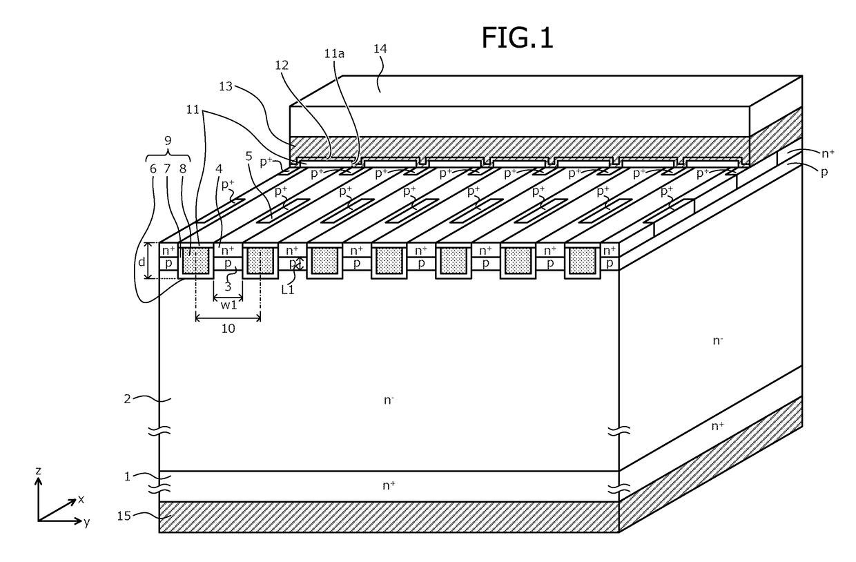
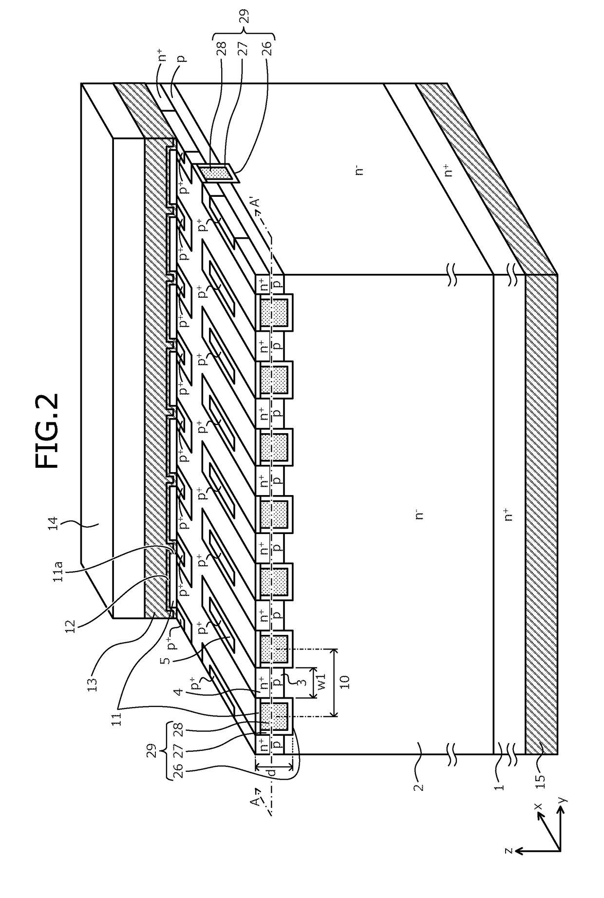
[0029]Embodiments of a semiconductor device according to the present invention will be described in detail with reference to the accompanying drawings. In the present description and accompanying drawings, layers and regions prefixed with n or p mean that majority carriers are electrons or holes. Additionally, + or − appended to n or p means that the impurity concentration is higher or lower, respectively, than layers and regions without + or −. In the description of the embodiments below and the accompanying drawings, main portions that are identical will be given the same reference numerals and will not be repeatedly described. Further, in the present description, when Miller indices are described, “−” means a bar added to an index immediately after the “−”, and a negative index is expressed by prefixing “−” to the index.

[0030]The semiconductor device according to a first embodiment is a metal oxide semiconductor (MOS) semiconductor device configured using a wide bandgap semicondu...


PUM


Abstract

On a front surface of an n+-type SiC substrate becoming a drain region, an n-type drift layer, a p-type base layer, and an n+-type source layer are sequentially formed by epitaxial growth. In the n+-type source layer, the p+-type contact region is selectively provided. A trench is provided penetrating the n+-type source layer and the p-type base layer in the depth direction and reaching the n-type drift layer. In the trench, a gate electrode is provided via a gate insulating film. A width between adjacent trenches is, for example, 1 μm or less. A depth of the trench is, for example, 1 μm or less. The width is narrow whereby substantially the entire p-type base layer forms a channel. A cell includes a FinFET structure in which one channel is sandwiched between MOS gates on both side. Thus, ON resistance may be reduced and decreased reliability may be prevented.

Description

CROSS REFERENCE TO RELATED APPLICATIONS[0001]This is a continuation application of International Application PCT / JP2016 / 073369 filed on Aug. 8, 2016 which claims priority from a Japanese Patent Application No. 2015-183480 filed on Sep. 16, 2015, the contents of which are incorporated herein by reference.BACKGROUND OF THE INVENTION1. Field of the Invention[0002]Embodiments of the present invention related to a semiconductor device.2. Description of the Related Art[0003]Silicon (Si) has been used as a constituent material of power semiconductor devices that control high voltage and / or large current. There are several types of power semiconductor devices such as bipolar transistors, insulated gate bipolar transistors (IGBTs), metal oxide semiconductor field effect transistors (MOSFETs), etc. These devices are selectively used according to an intended purpose.[0004]For example, bipolar transistors and IGBTs have high current density compared to MOSFETs, and can be adapted for large curr...

Claims


Application Information

Patent Timeline
Patent Type & Authority Applications(United States)
IPC IPC(8): H01L29/16H01L29/45H01L29/66H01L29/78
CPCH01L29/1608H01L29/7813H01L29/66795H01L29/456H01L29/785H01L29/66734H01L29/0696H01L29/1095H01L29/2003H01L29/41766H01L29/12
Inventor HOSHI, YASUYUKIOTSUKI, MASAHITOYAMADA, SHOJISHIIGI, TAKASHI
Owner FUJI ELECTRIC CO LTD
Why Eureka
Try Eureka