
Method for very high throughput satellite data transmission

Active Publication Date: 2017-12-21
THALES SA
View PDF5 Cites 3 Cited by
  • Summary
  • Abstract
  • Description
  • Claims
  • Application Information

AI Technical Summary

Benefits of technology

The invention aims to improve data transmission methods, make processing operations simpler, reduce the amount of processing power needed, and increase the efficiency of uplink spectrum.

Problems solved by technology

However, in the very high throughput transmission systems, the use of a transparent processor is often unsuitable for transporting the necessary high throughput, because of a lack of frequency resources.
To mitigate this problem, the current trend is to use wider frequency bands like the V and Q bands, but that causes the link budget to be degraded.
This necessitates the use of geographical diversity mechanisms, which leads to an increased complexity of the equipment used in the gateway station and greatly increases the cost of the transmission system.
The current regenerative processors are very complex because, because of the stack of the protocol layers used for the transmission of the data, it is necessary to perform, on board the satellite, a complete demodulation of the data received over the uplink, a switching and a routing of all the IP packets, then a complete re-modulation of the data to be transmitted over the downlink.
Since the processing operations on board the satellite are performed on each IP packet, they are intensive and complex and require very significant on board computation power and processing power, which leads to electrical consumption and heat dissipation that are all the greater when the throughput of the data to be transmitted is high.
The problem is that the processing capacity and the power available on board a satellite is limited and is not suited to very high throughputs.

Method used


Image

  • Method for very high throughput satellite data transmission
  • Method for very high throughput satellite data transmission
  • Method for very high throughput satellite data transmission

Examples


Embodiment Construction

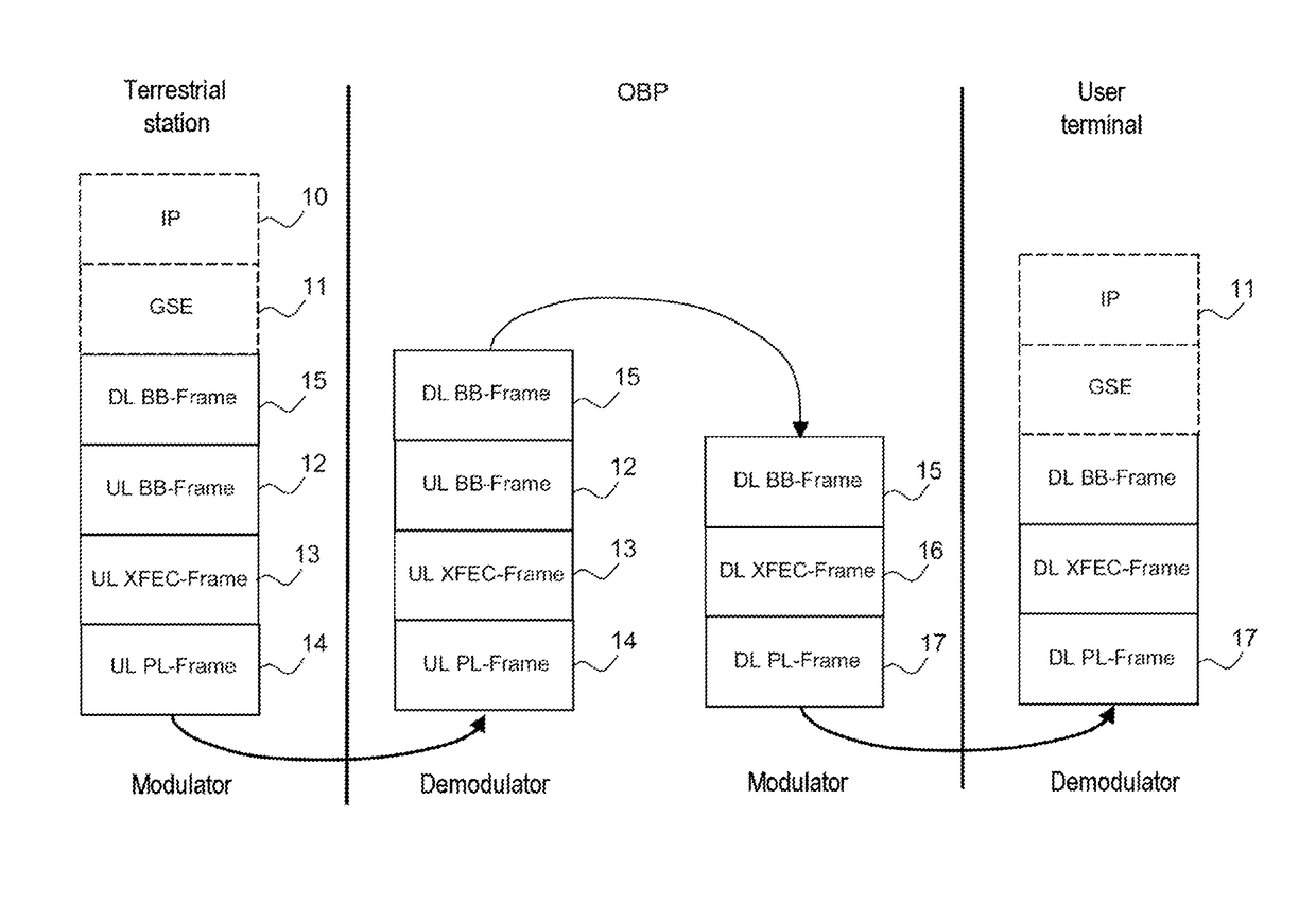
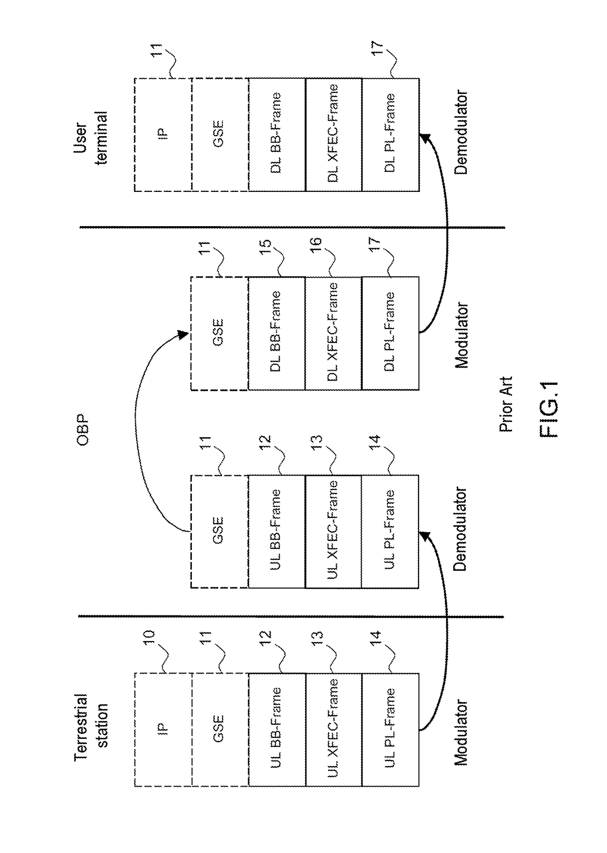
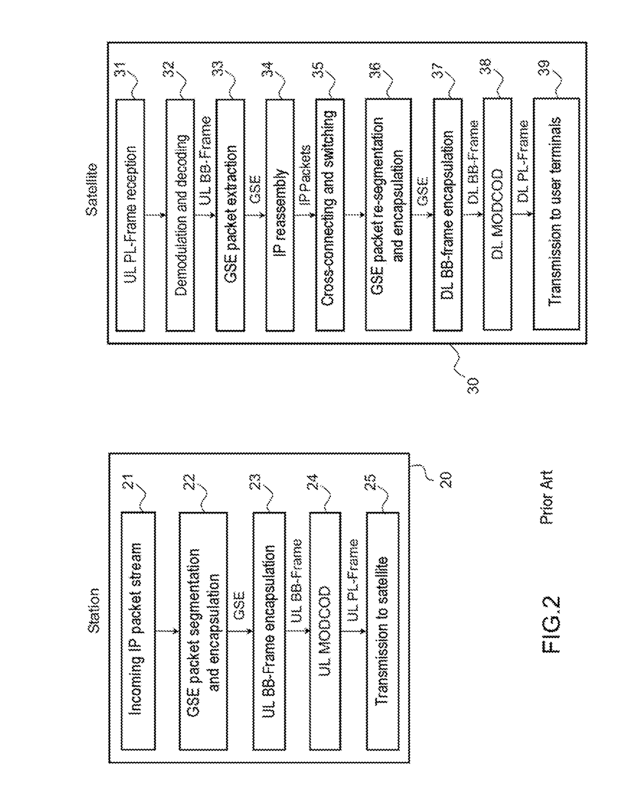
[0022]FIG. 1 illustrates an example of a stack of the protocol layers, transmitted by a gateway station, received and transmitted by a receiver / transmitter on board a satellite and received by a user terminal, according to the prior art. In this example, the stack of the protocol layers uses the DVB-S2 (digital video broadcasting-second generation) standard. The diagram comprises four different columns. The column on the left shows the stack of the successive protocol layers transmitted by a gateway station, the two central columns represent the stack of the successive protocol layers received by the receiver / transmitter on board the satellite and respectively the stack of the successive protocol layers retransmitted to the users after processing on board the satellite, the column on the right illustrates the stack of the successive protocol layers received by the users. FIG. 2 illustrates a block diagram of an example of a satellite data transmission method, the method being called...


PUM


Abstract

A method comprises a preprocessing step consisting, in the gateway station, in pre-segmenting the data as a function of the carrier frequency which is dedicated to them on the downlink DL, in reassembling and in encapsulating the pre-segmented data in successive basic frames DL BB-Frames, that can be transmitted over the downlink, each basic frame DL BB-Frame of the downlink being encapsulated by addition of a specific transport header DL BB-TH on the downlink and a data field, and a step consisting, in the gateway station, in incorporating the different basic frames DL BB-Frames of the downlink in the data field of the different basic frames UL BB-Frames of the uplink.

Description

CROSS-REFERENCE TO RELATED APPLICATIONS[0001]This application claims priority to foreign French patent application No. FR 1600959, filed on Jun. 16, 2016, the disclosure of which is incorporated by reference in its entirety.FIELD OF THE INVENTION[0002]The present invention relates to an improved satellite data transmission method. It applies to any satellite telecommunication system and in particular to very high throughput transmission systems of HTS or VHTS (very high throughput satellite) type.BACKGROUND[0003]A satellite telecommunication system comprises uplinks between gateway stations GS and an OBP processor (on board processor) mounted on board a satellite and downlinks between the OBP processor and user terminals. Generally, the uplink has a link budget, that is to say a signal-to-noise ratio, which is much better than the downlink. The OBP processor can be a transparent processor or a regenerative processor.[0004]In the case where the OBP processor is transparent, the wavef...

Claims


Application Information

Patent Timeline
IPC IPC(8): H04L12/46H04B7/15H04L12/66H04L29/06H04L47/43
CPCH04L12/4633H04L69/22H04L12/66H04B7/15H04B7/18517H04B7/18582
Inventor ARNAUD, MATHIEUBAUDOIN, CEDRICNIDDAM, DAVIDLAUTIER, PATRICK
Owner THALES SA
Learn More