Prosthetic Heart Valve with Compressible Frames

a heart valve and frame technology, applied in the field of valve replacement, can solve the problems of increasing total stroke volume and reducing cardiac outpu

Active Publication Date: 2017-12-28
CARDIOVALVE LTD
View PDF5 Cites 84 Cited by
  • Summary
  • Abstract
  • Description
  • Claims
  • Application Information

AI Technical Summary

Benefits of technology

[0005]For some applications, an implant is provided having a tubular portion, an upstream support portion and one or more flanges. The implant is percutaneously deliverable to a native heart valve in a compressed state, and is expandable at the native valve. The implant and its delivery system facilitate causing the upstream support portion and the flanges to protrude radially outward from the tubular portion without expanding the tubular portion. Expansion of the tubular portion brings the upstream support portion and the flanges closer together, for securing the implant at the native valve by sandwiching tissue of the native valve between the upstream support portion and the flanges.

Problems solved by technology

Regurgitation of blood from the ventricle into the atrium results in increased total stroke volume and decreased cardiac output, and ultimate weakening of the ventricle secondary to a volume overload and a pressure overload of the atrium.

Method used


Image

  • Prosthetic Heart Valve with Compressible Frames
  • Prosthetic Heart Valve with Compressible Frames
  • Prosthetic Heart Valve with Compressible Frames

Examples


Embodiment Construction

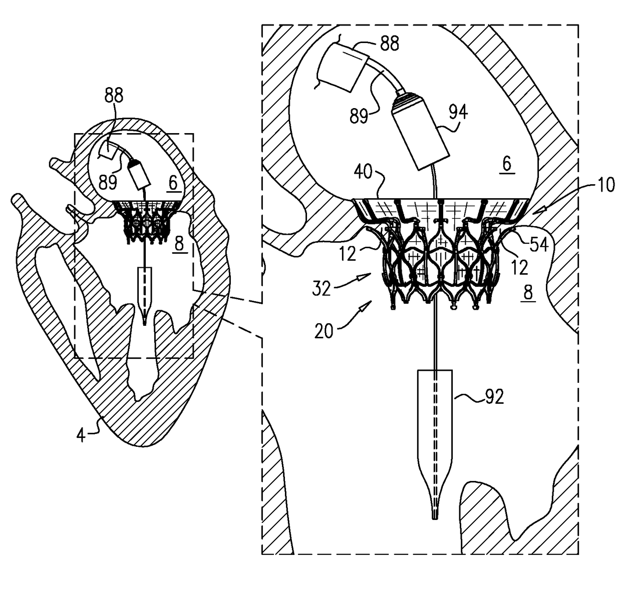
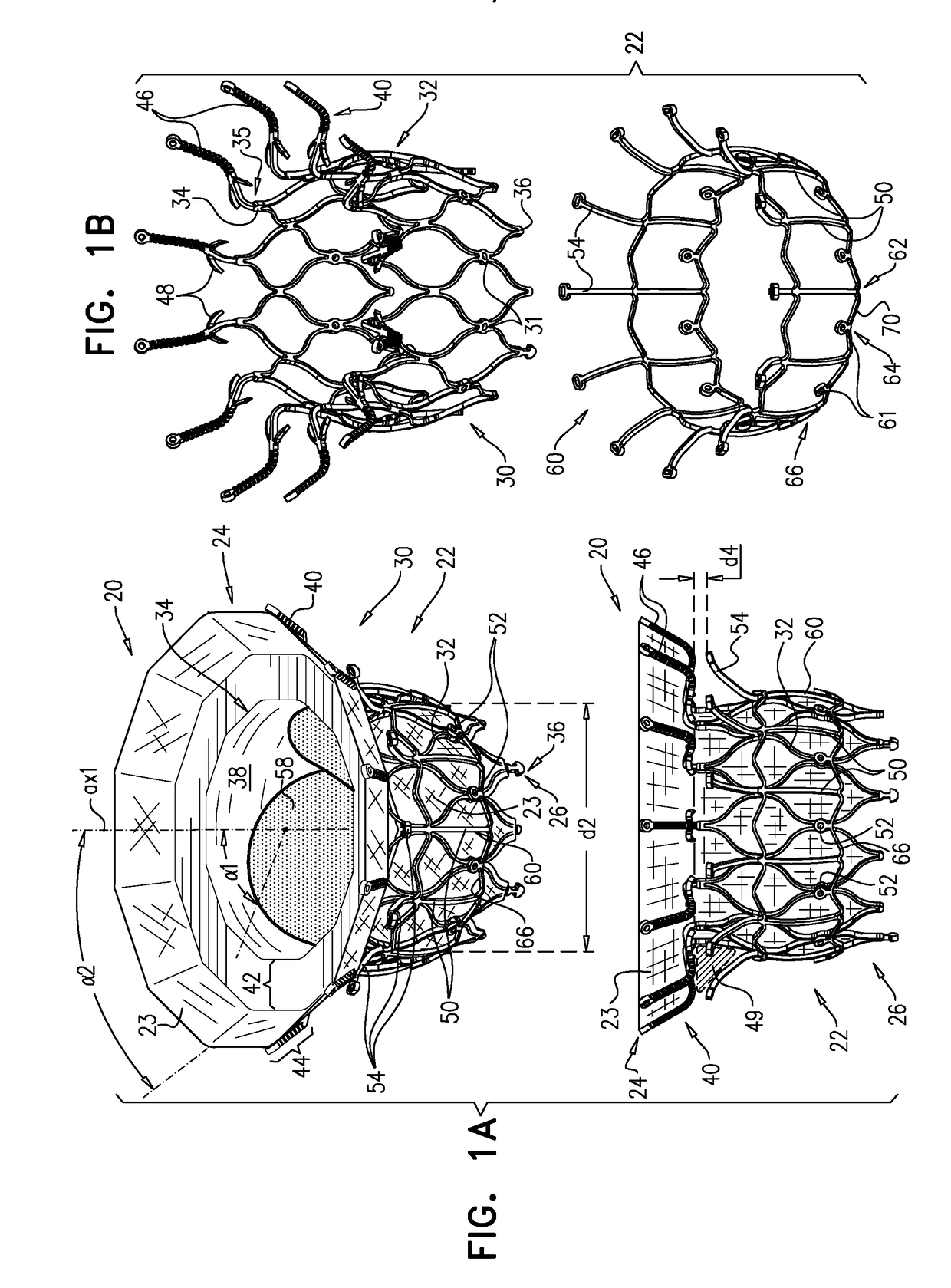
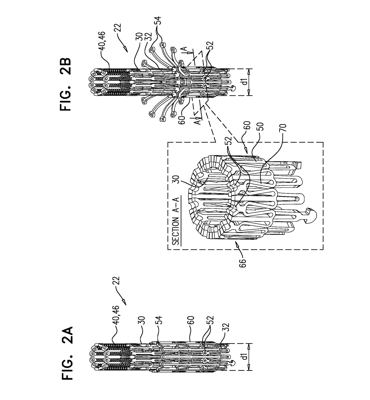
[0292]Reference is made to FIGS. 1A-B and 2A-E, which are schematic illustrations of an implant 20 for use with a native valve of a heart of a subject, in accordance with some applications of the invention. Implant 20 comprises a frame assembly 22 that has an upstream end 24, a downstream end 26, and a central longitudinal axis ax1 therebetween. Frame assembly 22 comprises a valve frame 30 that comprises a tubular portion 32 that has an upstream end 34 and a downstream end 36, and is shaped to define a lumen 38 through the tubular portion from the upstream end to the downstream end. Tubular portion 32 circumscribes axis ax1, and thereby defines lumen 38 along the axis. Valve frame 30 further comprises an upstream support portion 40, extending from upstream end 34 of tubular portion 32. Frame assembly 22 further comprises at least one leg 50, coupled to valve frame 30 at (e.g., via) a coupling point 52, and having a tissue-engaging flange 54.

[0293]Typically, and as described herein b...


PUM


Abstract

A tubular portion of a valve frame circumscribes a longitudinal axis, and defines a lumen along the axis and a plurality of valve-frame coupling elements disposed circumferentially around the axis. An outer frame: (a) comprises a ring defined by a pattern of alternating peaks and troughs, the pattern having an amplitude, (b) comprises a plurality of legs, coupled to the ring at respective troughs, and (c) is shaped to define a plurality of outer-frame coupling elements, each coupled to the ring, and fixed with respect to a respective valve-frame coupling element. Compression of the tubular portion from an expanded state toward a compressed state reduces a circumferential distance between each of the outer-frame coupling elements and its adjacent outer-frame coupling elements, and increases the amplitude of the pattern of the ring.

Description

CROSS-REFERENCES TO RELATED APPLICATIONS[0001]This application is a continuation of U.S. patent application Ser. No. 15 / 541,783 to Hariton et al., filed Jul. 6, 2017, and entitled “Prosthetic valve with axially-sliding frames,” which is a US National Phase of PCT application IL2016 / 050125 to Hariton et al., filed Feb. 3, 2016, and entitled “Prosthetic valve with axially-sliding frames,” which published as WO 2016 / 125160, and which claims priority from U.S. Provisional Patent Application 62 / 112,343 to Hariton et al., filed Feb. 5, 2015, and entitled “Prosthetic valve with axially-sliding frames,” which is incorporated herein by reference.FIELD OF THE INVENTION[0002]Some applications of the present invention relate in general to valve replacement. More specifically, some applications of the present invention relate to prosthetic valves for replacement of a cardiac valve.BACKGROUND[0003]Ischemic heart disease causes regurgitation of a heart valve by the combination of ischemic dysfunct...

Claims


Application Information

Patent Timeline
Patent Type & Authority Applications(United States)
IPC IPC(8): A61F2/24
CPCA61F2/2436A61F2/2418A61F2220/0016A61F2220/0025A61F2/9517A61F2/2409A61F2/243A61F2002/91575
Inventor HARITON, ILIAHARARI, BOAZ
Owner CARDIOVALVE LTD
Why Eureka
Try Eureka