Multi-mode unmanned aerial vehicle

a multi-mode, unmanned aerial technology, applied in the direction of vertical landing/take-off aircraft, aircraft, transportation and packaging, etc., can solve the problems of large amount of fuel required to achieve full throttle, performance and safety issues of helicopters, and the performance of helicopters is limited by their forward speed

Inactive Publication Date: 2017-12-28
ALZAHRANI SAEID A
View PDF0 Cites 58 Cited by
  • Summary
  • Abstract
  • Description
  • Claims
  • Application Information

AI Technical Summary

Benefits of technology

[0008]In one embodiment, a multi-mode unmanned aerial vehicle includes an elongated fuselage having a front end, a rear end with a curved guide slot, a right side, a left side, and a WIG-effect bottom; a right-fixed wing extending from the right side of the elongated fuselage; a right tilt wing attached at a first side to a free end of the right fixed wing, the right tilt wing being rotatable in a range of 0-135 degrees about a lateral axis of the multi-mode unmanned aerial vehicle; a right duct attached to a second side of the right tilt wing; a right winglet attached to the right duct opposite to the right tilt wing; a left-fixed wing extending from the left side of the elongated fuselage; a left tilt wing attached at a first side to a free end of the left fixed wing, the left tilt wing being rotatable in a range of 0-135 degrees about the lateral axis of the multi-mode unmanned aerial vehicle; a left duct attached to a second side of the left tilt wing; a left winglet attached to the left duct opp...

Problems solved by technology

One challenge has been to design an aerial vehicle that can take-off, land, and hover like a helicopter and also possess speed, range, payload capacity, and operational features of a fixed-wing aircraft.
However, one problem of this aerial vehicle is the large amount of fuel required to accomplish full throttle for the aerial vehicle to hover.
However, there are performance and safety issues with a helicopter.
The performance of a helicopter is limite...

Method used


Image

  • Multi-mode unmanned aerial vehicle
  • Multi-mode unmanned aerial vehicle
  • Multi-mode unmanned aerial vehicle

Examples


Embodiment Construction

[0050]There is a need to develop simple, safe, and fully or semi-autonomous UAVs for a range of military and commercial applications with the ability to take-off and land vertically in complex urban areas and provide satisfactory horizontal speed to accomplish longer forward flight endurance.

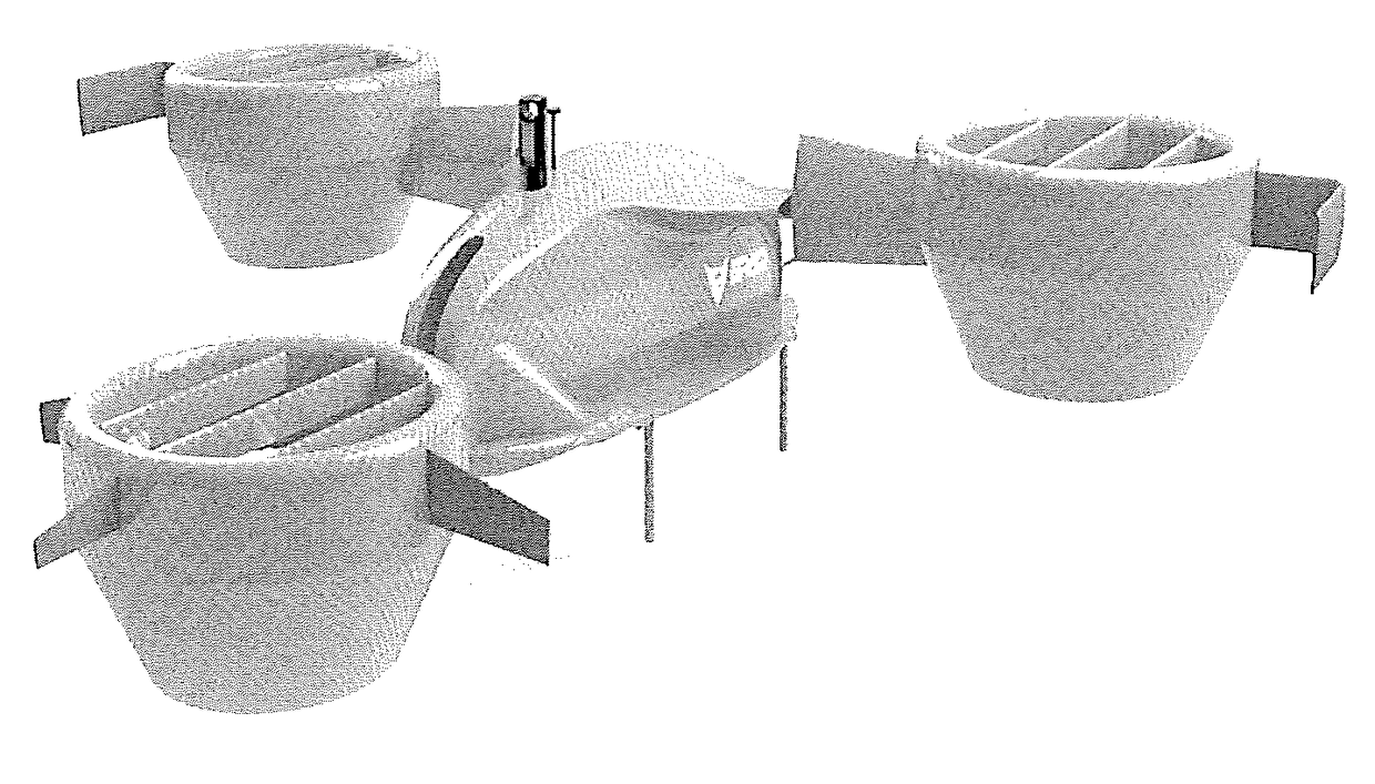
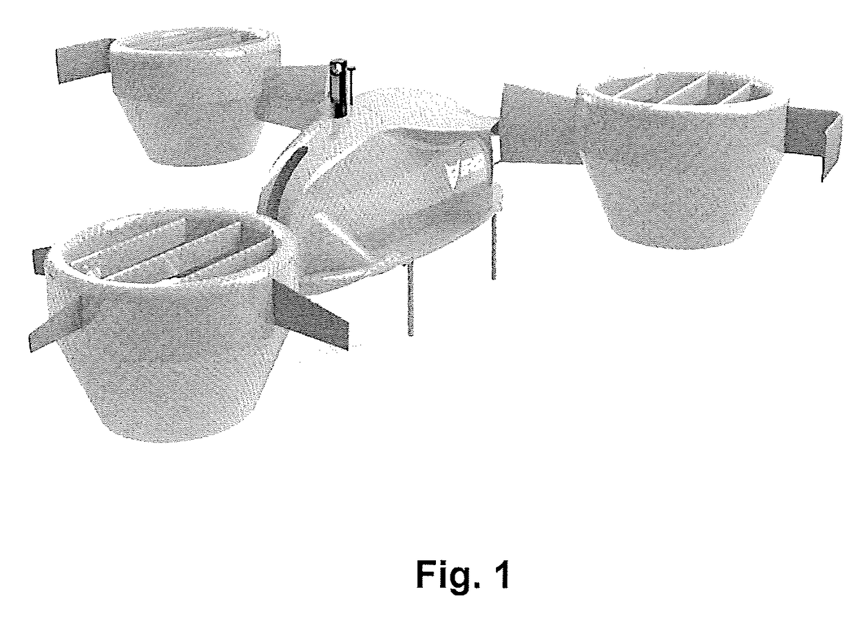
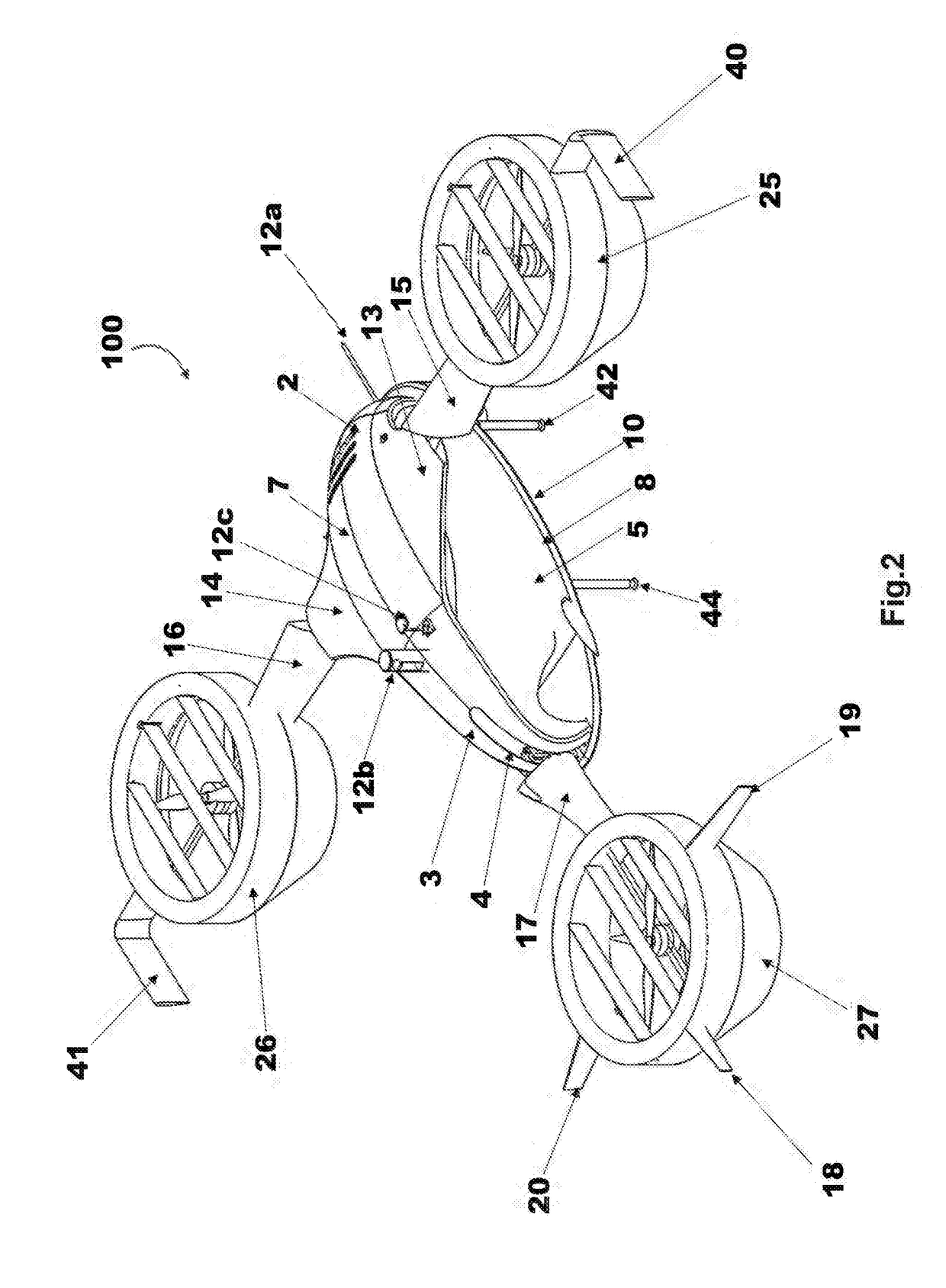
[0051]Embodiments described herein provide a multi-mode unmanned aerial vehicle that is capable of vertical take-off and landing (VTOL), short take-off and landing (STOL), horizontal take-off and landing (HTOL), and configured to skim, boat, and cruise over water surfaces. In an embodiment, the multi-mode UAV is a fully or semi-autonomously controlled, and gyroscopically stabilized multi-purpose (sky-land-sea) UAV. The multi-mode UAV can take off and land from a wide variety of locations without the requirement of an airport runway or a landing pad.

[0052]Current-day military and commercial UAV applications make it desirable to deploy a ducted fan UAV in which the overall flight safety is improve...


PUM


Abstract

A multi-mode unmanned aerial vehicle includes an elongated fuselage, a right and left fixed wing extending from a respective right and left side of the elongated fuselage, a right and left tilt wing attached at a first side to a free end of the respective right and left fixed wing, a right and left duct attached to a second side of the respective right and left tilt wing, a right and left winglet attached to the respective right and left duct opposite to the right and left tilt wing, a tilt tail located within a curved guide slot at a rear end of the elongated fuselage, a rear duct attached to the tilt tail, a tilting mechanism, and an integrated autonomous flight control system.

Description

RELATED APPLICATION[0001]This application is a continuation-in-part of U.S. application Ser. No. 15 / 195,238, filed on Jun. 28, 2016, which is incorporated by reference herein in its entirety.GRANT OF NON-EXCLUSIVE RIGHT[0002]This application was prepared with financial support from the Saudi Arabian Cultural Mission, and in consideration therefore the present inventor(s) has granted The Kingdom of Saudi Arabia a non-exclusive right to practice the present invention in the United States.BACKGROUNDDescription of Related Art[0003]The aviation industry has worked at improving vertical take-off and landing (VTOL) and short take-off and landing (STOL) aerial vehicles. The use of VTOL / STOL aerial vehicles is significantly efficient. One challenge has been to design an aerial vehicle that can take-off, land, and hover like a helicopter and also possess speed, range, payload capacity, and operational features of a fixed-wing aircraft.[0004]The unmanned aerial vehicle (UAV) market is growing ...

Claims


Application Information

Patent Timeline
IPC IPC(8): B64C29/00B64C3/38B64C39/02B64C25/22B64C27/52
CPCB64C29/0033B64C25/22B64C39/024B64C27/52B64C2201/108B64C2201/141B64C2201/021B64C2201/027B64C2201/102B64C3/38B64U30/10B64U10/25B64U10/13B64U30/20B64U50/14
Inventor ALZAHRANI, SAEID A.
Owner ALZAHRANI SAEID A
Why Eureka
Try Eureka