Online tracer monitoring and tracer meter

a tracer and monitoring technology, applied in the field of tracer monitoring and tracer meter, can solve the problems of consuming time and laborious, and reducing the number of fluid samples to be analyzed

Inactive Publication Date: 2017-12-28
RESMAN AS
View PDF10 Cites 10 Cited by
  • Summary
  • Abstract
  • Description
  • Claims
  • Application Information

AI Technical Summary

Benefits of technology

[0057]One such extreme case is when a tracer is injected directly into the production tubing flow and the transport to surface is relatively dispersion-free (short and stable flow path). It may then be required to monitor with a sampling frequency of 0.2 Hz (one sample per 5 sec) to reconstruct the rapid flushout from the downhole production tubing. Another example is when two or more tracer carrying flows from different wells are commingled at a seafloor manifold, and at least one flow source is unstable, e.g. oil-water-gas rates are rapidly varying.

Problems solved by technology

But the AQUIREMENT of raw data is not necessarily done with the same speed as the Real-Time requirements of the DELIVERIES.
The present practice is a time consuming and demanding procedure.
There is also a cost component to it that leads to minimizing the number of fluid samples to be analyzed.
Thus, long campaigns will become unwieldy; the fluid samples may be manually withdrawn from the production flow by an operator, and the filling and handling of pre-marked bottles may take up to 4½ minutes to achieve the goal of 5 minutes fluid sampling frequency which is the goal of the present practice.
The harsh environment at the production fluid sampling site may easily incur a loss or untimely fluid sampling of one or more of the fluid samples.
A higher frequency of fluid sampling will be too difficult to carry out with present practice.
There are, due to under-sampling in the fluid sampling (too low fluid sampling frequency), too few data points in the beginning of the fluid sampling series to discern the zonal tracer flux flushout from the base pipe liner.

Method used


Image

  • Online tracer monitoring and tracer meter
  • Online tracer monitoring and tracer meter
  • Online tracer monitoring and tracer meter

Examples


Embodiment Construction

[0059]In the following the invention will be described with references to, but not limited to illustrations in the attached figures.

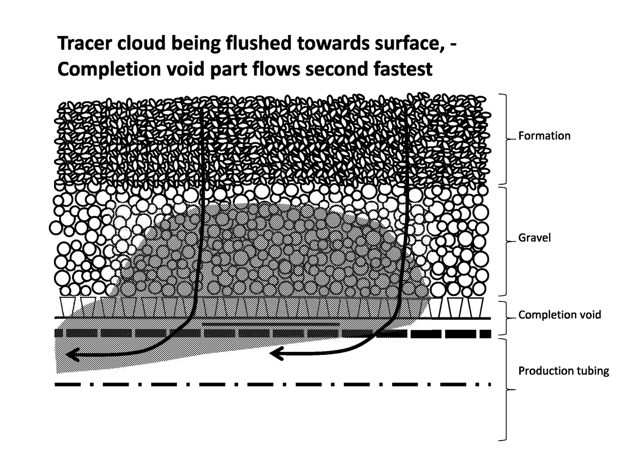
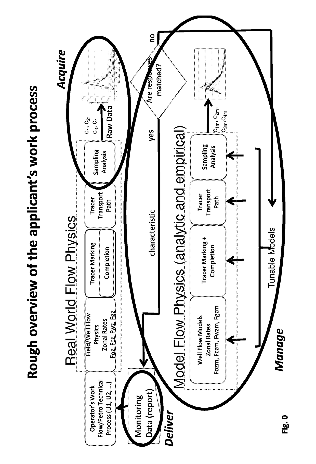
[0060]The applicants work process is related to ACQUIRE and MANAGE raw zonal tracer flux data and finally DELIVER usable information to customers. This invention relates to the ACQUISITION and a method and an apparatus for high frequency online monitoring of zonal tracer flux of oil-, condensate-, gas-, or water-following tracers in a production flow in a petroleum well so as for detecting tracer concentrations that corresponds to so-called “ultra-high frequency” zonal tracer flux signals.

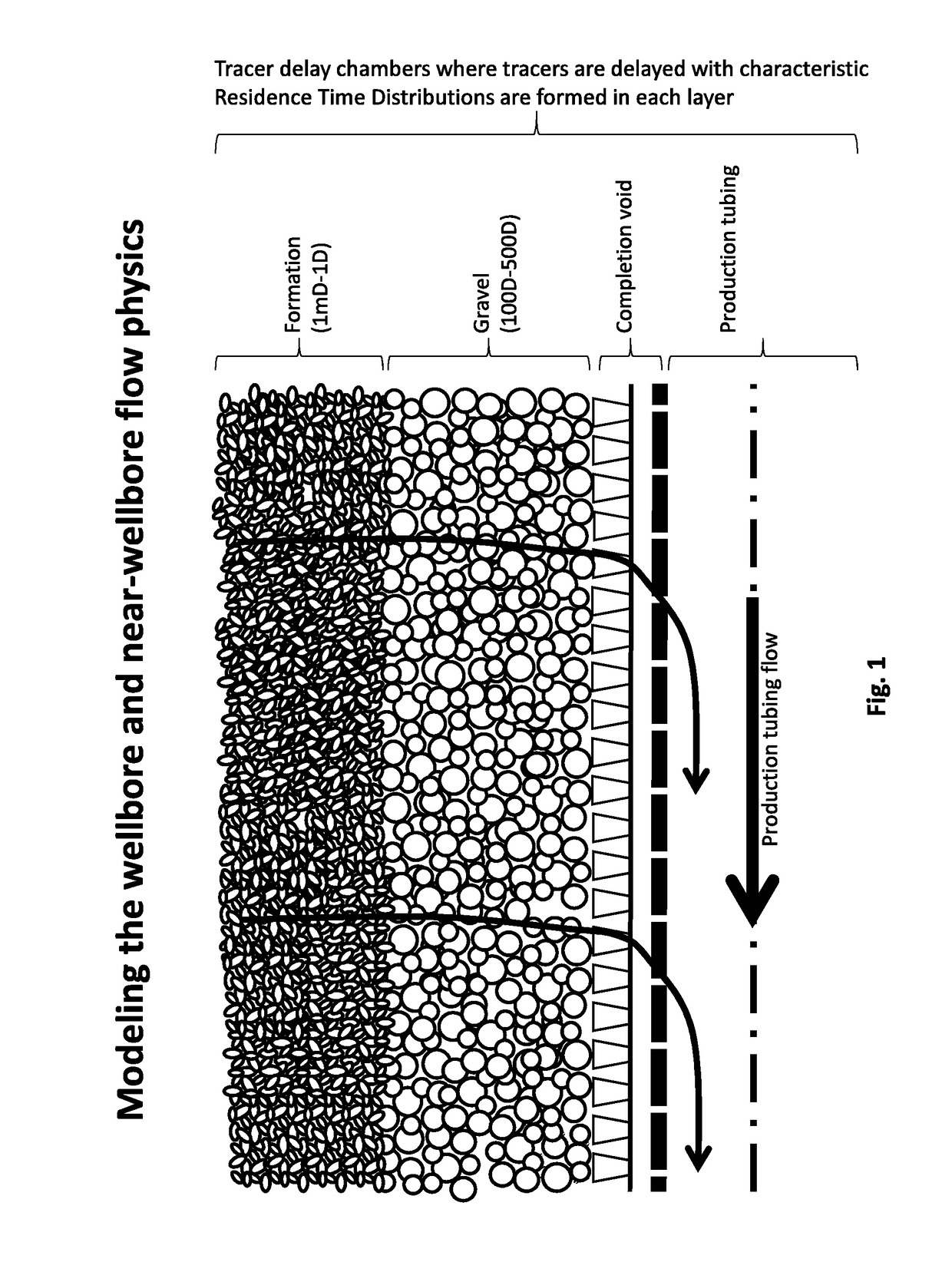
[0061]The invention is a tracer method for online monitoring of downhole zonal contributions of oil, condensate, gas, or water mass flux (Foz, Fcz, Fwz, Fgz) of a production flow (2) in a petroleum production well (1), comprising

[0062]a) arranging distinct tracer carrier systems (Trs1, Trs2, . . . ) each in different production zones (Z1, Z2, . . . ) in said well (1), ...


PUM


Abstract

A tracer method for online monitoring of downhole zonal contributions of oil, condensate, gas, or water mass flux of a production flow in a petroleum production well, includes arranging distinct tracer carrier systems, each in different production zones in said well, the distinct tracer carrier systems arranged for releasing unique tracers to a fluid of the production zones, the tracers having affinity after downhole release to separate phases of oil, condensate, gas, or water, using an online tracer monitor, conducting sampling of tracer concentrations for at least one of the tracers in said zonal mass fluxes at a high sampling rate, based on said concentration values, estimating the corresponding zonal tracer fluxes for each delivery data point and using said one or more estimated zonal mass fluxes to control one or more Petro Technical processes.

Description

INTRODUCTION[0001]The present invention relates to a method and an apparatus for online monitoring of tracer concentration of oil-, condensate-, gas-, or water-following tracers in a production flow in a petroleum well, if required, estimating the tracer flux, and with the objective of estimating downhole inflow profiles of one or more of the fluid phases.[0002]More specifically the invention is a method for high frequency online monitoring tracer concentration of oil-, condensate-, gas-, or water-following tracers in a production flow, comprising arranging distinct tracer carrier systems in different production zones in a well for releasing tracers to a fluid of the production zones, allowing all or part of a production flow of said well to be separated into two or more segregated fluids and using an online tracer monitoring system for measuring concentrations of possible said unique tracers in at least one of said segregated phases. The monitoring system may be based on a combinat...

Claims


Application Information

Patent Timeline
Patent Type & Authority Applications(United States)
IPC IPC(8): E21B47/10E21B43/38G01V15/00E21B49/08E21B34/06
CPCE21B47/1015E21B43/38E21B34/06G01V15/00E21B49/08E21B47/11E21B43/14
Inventor NYHAVN, FRIDTJOFSPERLE, THOMAS
Owner RESMAN AS
Why Eureka
Try Eureka