Reactor including tubular core, motor drive device, and amplifier device

a technology of motor drive device and amplifier device, which is applied in the direction of electrical apparatus, control system, dynamo-electric converter control, etc., can solve the problem of contributing to the temperature rise of the power cabin

Active Publication Date: 2017-12-28
FANUC LTD
View PDF5 Cites 6 Cited by
  • Summary
  • Abstract
  • Description
  • Claims
  • Application Information

AI Technical Summary

Problems solved by technology

Thus, the quantity of heat generated from the reactor accounts for all the resi...

Method used


Image

  • Reactor including tubular core, motor drive device, and amplifier device
  • Reactor including tubular core, motor drive device, and amplifier device
  • Reactor including tubular core, motor drive device, and amplifier device

Examples


Embodiment Construction

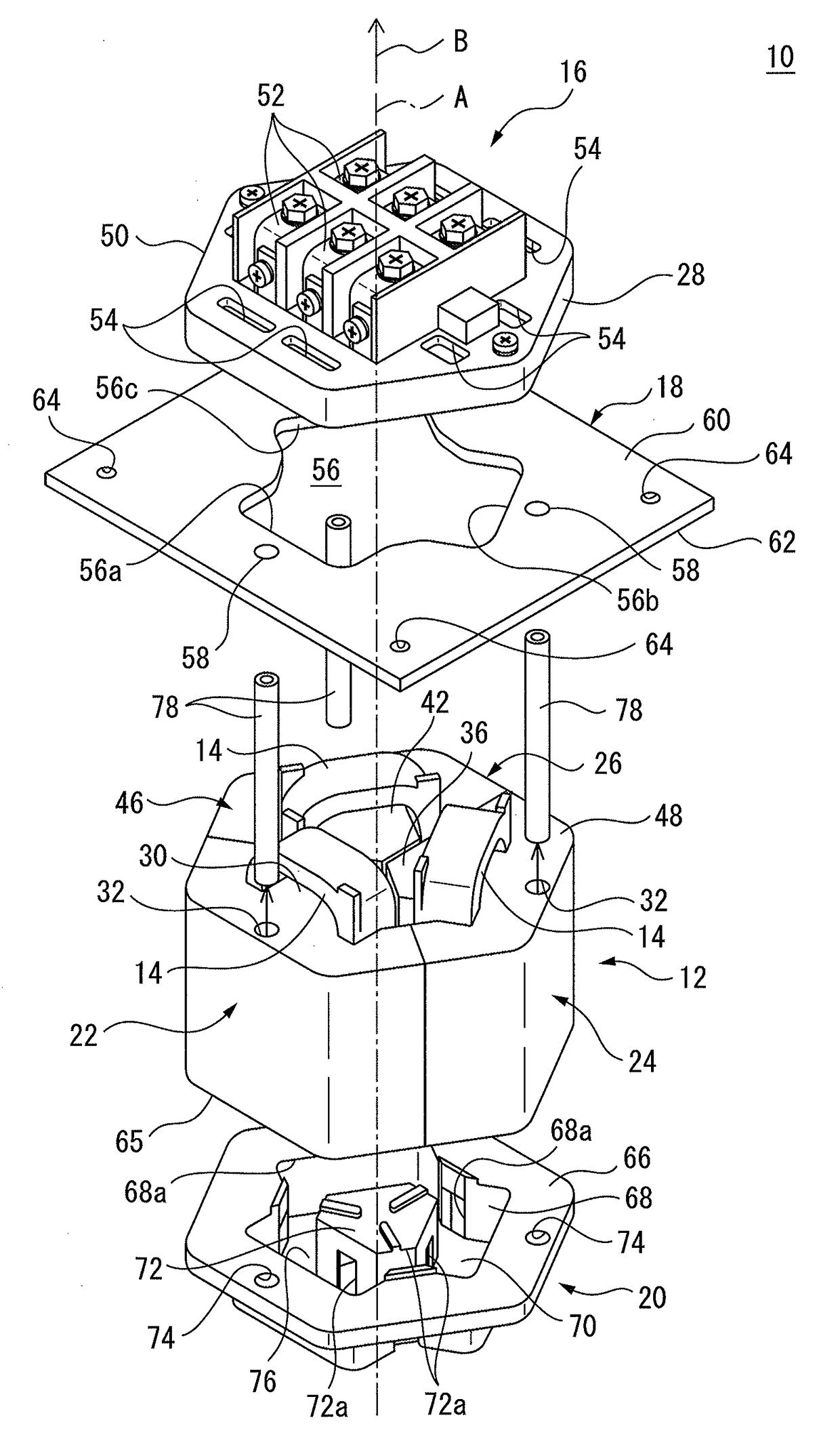
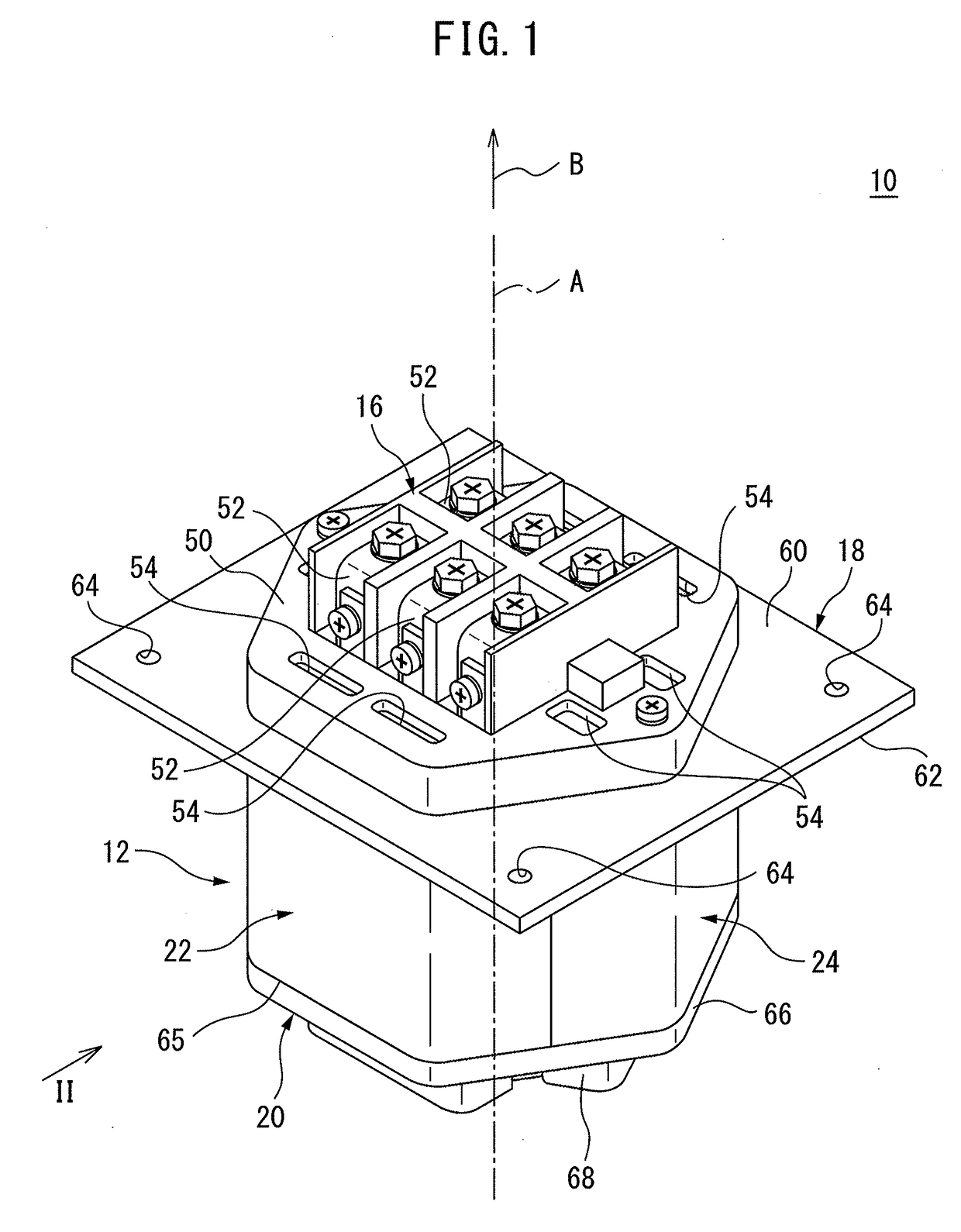
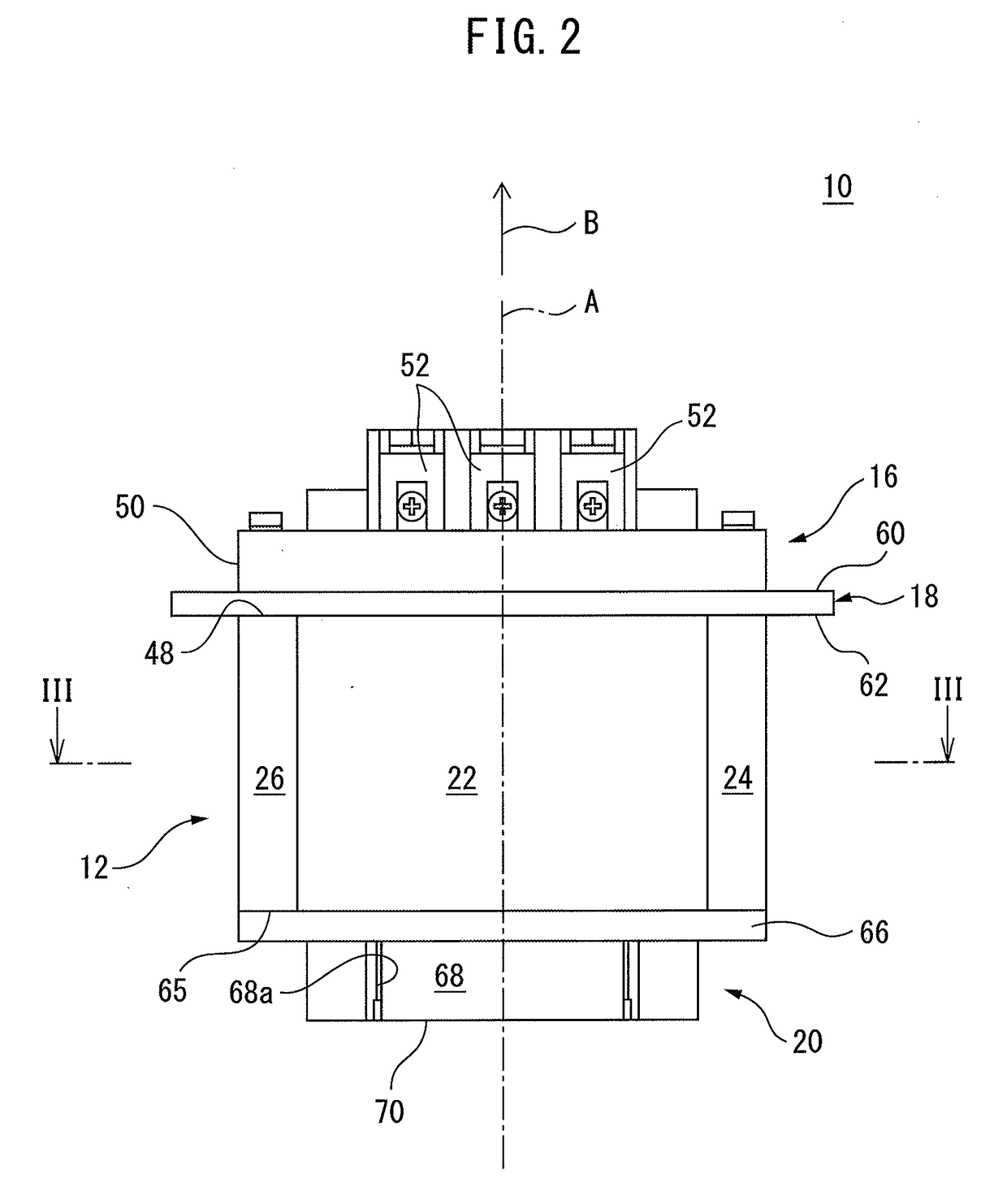
[0025]Embodiments of the invention will be described below with reference to the drawings. Note that, in various embodiments described below, similar elements are assigned the same reference numerals, and overlapping descriptions will be omitted. First, with reference to FIGS. 1 to 4, a reactor 10 according to an embodiment will be described.

[0026]Note that, the axial direction in the following description represents a direction along a center axis A of a core 12 of the reactor 10. Further, the radial direction represents a direction of radius of a circle centered about the axis A, and the circumferential direction represents the circumferential direction of the circle. Further, for the sake of convenience, the direction indicated by an arrow B in the drawings is referred to as the axially upward direction.

[0027]The reactor 10 is e.g. an alternating-current (AC) reactor, and includes the core 12, coils 14, a terminal block 16, an attachment flange 18, and a cover 20. The core 12 is ...


PUM


Abstract

A reactor capable of eliminating a heat source provided within a power cabinet housing a motor drive device. The reactor includes a tubular core, a coil installed inside the core, a terminal which is provided at an axially first end of the core and which is connected to the coil, and an attachment flange which extends radially outside of the core and which is provided between the terminal and a second end of the core.

Description

BACKGROUND OF THE INVENTION1. Field of the Invention[0001]The invention relates to a reactor including a tubular core, a motor drive device, and an amplifier device.2. Description of the Related Art[0002]In a machine tool or industrial machine, a motor drive device (including a converter, an inverter, and a reactor) for driving a motor used for a robot, the reactor disposed between the converter of the motor drive device and a power source is generally installed in a power cabinet.[0003]Peripheral equipment including a motor drive device installed in the power cabinet, or cables generate heat, and accordingly, the internal temperature of the power cabinet reaches 40° C. to 50° C. in some cases. Thus, an air duct for ventilation and a cooler may be provided to prevent the motor drive device or peripheral equipment from excessively generating heat.[0004]The quantity of heat generated from the motor drive device, the peripheral equipment, and the cables in the power cabinet is referred...

Claims


Application Information

Patent Timeline
IPC IPC(8): H01F27/06
CPCH02P2201/00H01F27/06
Inventor SHIROUZU, MASATOMO
Owner FANUC LTD
Why Eureka
Try Eureka