Beam-steering system of high-gain antenna using paraelectric material

Active Publication Date: 2017-12-28
HONGIK UNIV IND ACAD COOP FOUND
View PDF5 Cites 2 Cited by
  • Summary
  • Abstract
  • Description
  • Claims
  • Application Information

AI Technical Summary

Benefits of technology

[0019]According to the exemplary embodiment of the present disclosure, since relative permittivity can be controlled by using the paraelectric material whose permittivity varies depending on the applied voltage, phase control of a transmitted radio wave becomes possible, and therefore beam steering of a desired direction can be accomplished. Further, antenna gain can be enhanced by using a partially reflective surface (PRS).
[0020]Further, according to the exemplary embodiment of th

Problems solved by technology

However, as the number of antennas increases, the power supply structure becomes more complicated.
Particularly, in the millimeter wave band such as 5G mob

Method used


Image

  • Beam-steering system of high-gain antenna using paraelectric material
  • Beam-steering system of high-gain antenna using paraelectric material
  • Beam-steering system of high-gain antenna using paraelectric material

Examples


Embodiment Construction

[0028]Hereinafter, a beam steering system of a high-gain antenna using a paraelectric material according to an exemplary embodiment of the present disclosure will be described in detail with reference to the accompanying drawings. In the drawings, the thickness and dimensions of elements may be exaggerated for better comprehension and ease of description.

[0029]Further, the terminologies to be described below are ones defined in consideration of their function in the present disclosure and may be changed by the intention of a user or an operator, or a custom. Therefore, their definition should be made on the basis of the description of the present disclosure.

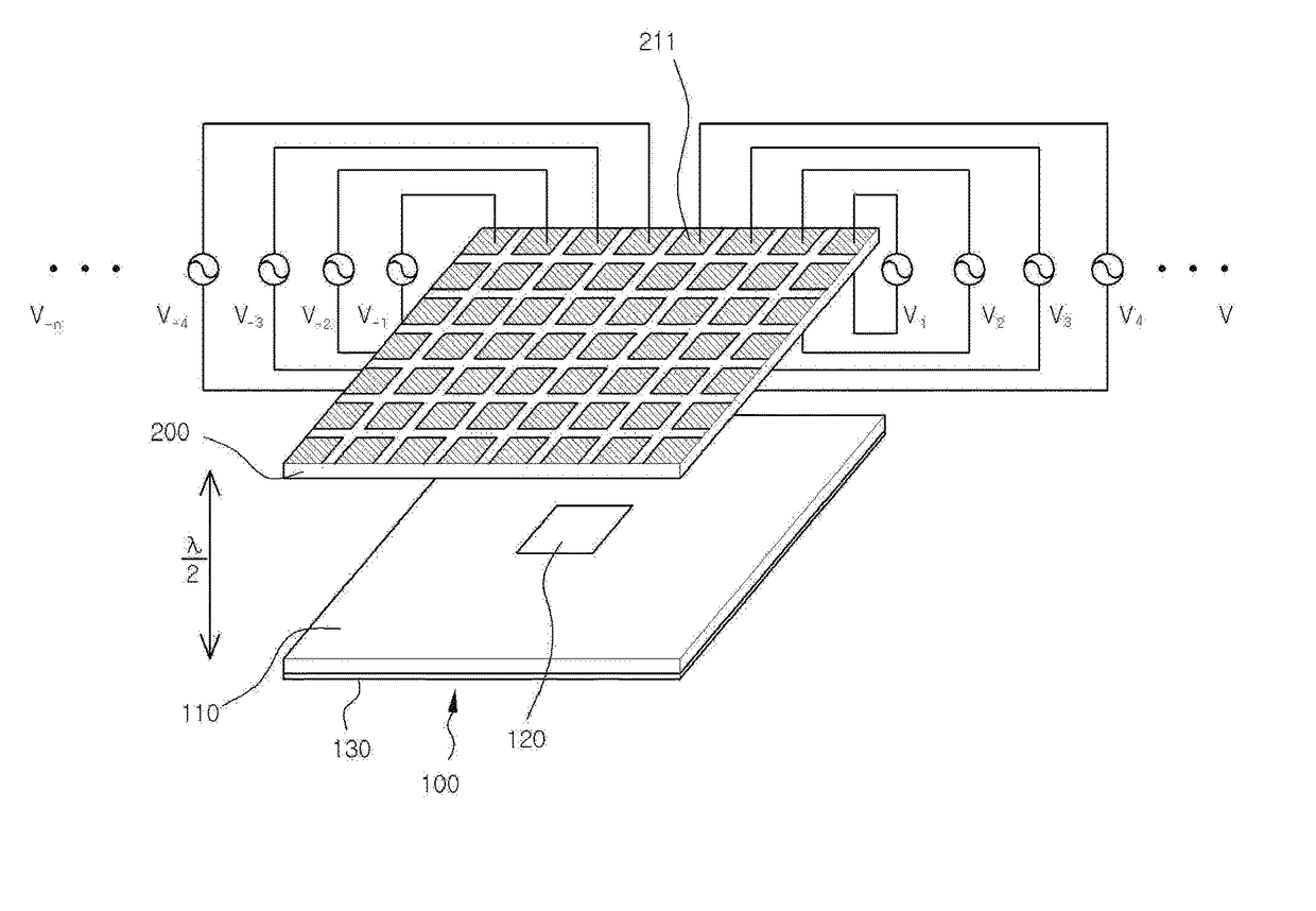
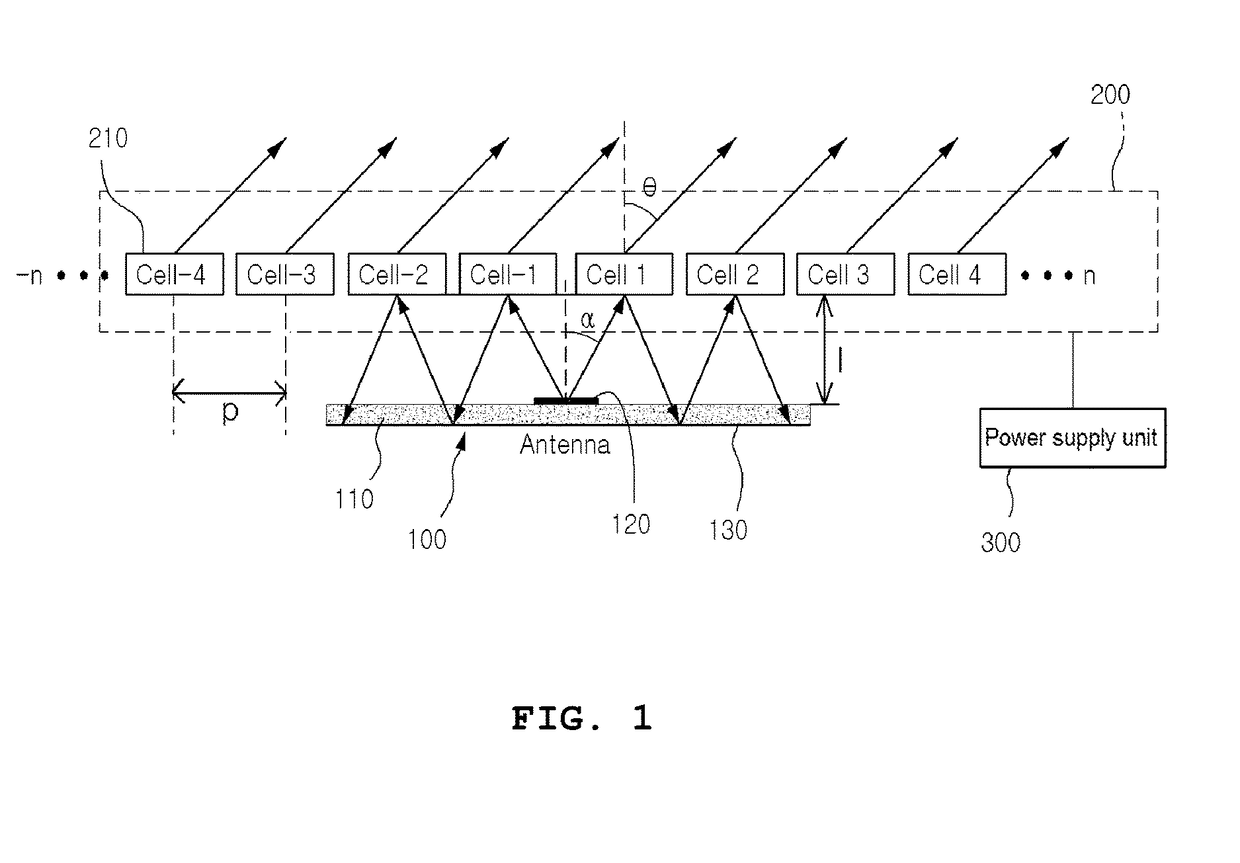
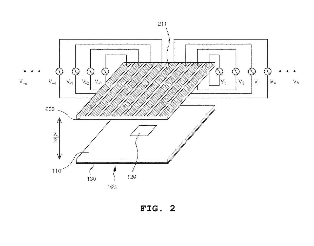
[0030]FIG. 1 is a schematic view of a beam steering system of a high-gain antenna using a paraelectric material according to an exemplary embodiment of the present disclosure.

[0031]Referring to FIG. 1, the beam steering system according to the exemplary embodiment of the present disclosure includes an antenna 100, a paraelectric ...


PUM


Abstract

A beam steering system of a high-gain antenna includes an antenna configured to include a printed circuit board in which an antenna element is designed, and a ground plane, wherein the printed circuit board and the ground plane may be each adhered onto upper and lower surfaces of the antenna; a paraelectric material configured to be separated from the upper surface of the antenna with a predetermined distance and is divided into a plurality of cells, whose relative permittivity varies depending on a voltage applied to a pair of thin metallic conductor patches adhered to upper and lower surfaces of each cell; and a power supply unit configured to supply the voltage to the pair of thin metallic conductor patches which are each adhered to the upper and lower surfaces of the cell to face each other.

Description

CROSS-REFERENCE TO RELATED APPLICATION[0001]This application claims priority to and the benefit of Korean Patent Application No. 10-2016-0080746, filed in the Korean Intellectual Property Office on Jun. 28, 2016, the entire contents of which are incorporated herein by reference.BACKGROUND OF THE INVENTION(a) Field of the Invention[0002]The present disclosure relates to a system of a beam-steering system of a high-gain antenna using a paraelectric material. More particularly, the present disclosure relates to a beam-steering system of a high-gain antenna which controls a phase of a transmitted radio wave by using a paraelectric material whose relative permittivity varies depending on an applied voltage.(b) Description of the Related Art[0003]A microstrip patch antenna is a type of planar antenna which is fabricated in the form of a printed circuit board (PCB). This antenna is appropriate for mass-production, and is very solid due to its planar structure with a very low profile. Due t...

Claims


Application Information

Patent Timeline
IPC IPC(8): H01Q13/10H01Q1/36H01Q1/48H01Q3/24
CPCH01Q13/106H01Q1/36H01Q3/24H01Q1/48H01Q3/46H01Q15/147H01Q3/26H01Q3/34H01Q21/10
Inventor LEE, JEONG-HAELEE, JAE-GON
Owner HONGIK UNIV IND ACAD COOP FOUND
Why Eureka
Try Eureka