Lamp control device

a control device and control device technology, applied in the direction of electroluminescent light sources, transportation and packaging, lighting and heating apparatus, etc., can solve the problems of noise introduction into the control device, increase the power loss, etc., to reduce the slope of the channel current, reduce the emi, and reduce the power loss

Active Publication Date: 2017-12-28
SILICON WORKS CO LTD
View PDF2 Cites 4 Cited by
  • Summary
  • Abstract
  • Description
  • Claims
  • Application Information

AI Technical Summary

Benefits of technology

[0007]Various embodiments are directed to a lamp control device capable of reducing a power loss caused by heat generation of an LED channel.
[0008]Also, various embodiments are directed to a lamp control device capable of retaining a channel current as a target current while reducing the size of a channel resistor.
[0018]According to the embodiments of the present invention, the lamp control device can reduce the value of the channel resistor in the LED channel, thereby reducing a power loss caused by heat generation the channel resistor.
[0019]Since the lamp control device boosts the channel resistor voltage lowered by the value of the channel resistor and drives the LED channel, the lamp control device can retain the channel current as the target current even though the channel resistor is designed to have a low value.
[0020]The lamp control device can reduce the slope of the channel current at the point of time that the LED channel is enabled / disabled, thereby reducing EMI which may be caused by switching operations of the channel switch.
[0021]Since the slope of the channel current is varied according to the PWM (Pulse Width Modulation) dimming duty of the LED channel, a flat section of the channel current can be secured even at a significantly small or large duty, which makes it possible to perform current control with precision.

Problems solved by technology

The channel resistors may generate heat when a channel current flows therethrough, and the heat generated by the channel resistors may increase a power loss.
When the channel resistors are removed to reduce a power loss, noise may be introduced into a lamp control device.
However, since the repeated switching operations for driving the LED channels accompany a rapid voltage change, the repeated switching operations may serve as a main factor to cause EMI (Electro Magnetic Interference).

Method used


Image

  • Lamp control device
  • Lamp control device
  • Lamp control device

Examples


Embodiment Construction

[0031]Hereafter, embodiments of the present invention will be described in detail with reference to the accompanying drawings. The terms used in the present specification and claims are not limited to typical dictionary definitions, but must be interpreted into meanings and concepts which coincide with the technical idea of the present invention.

[0032]Embodiments described in the present specification and configurations illustrated in the drawings are preferred embodiments of the present invention, and do not represent the entire technical idea of the present invention. Thus, various equivalents and modifications capable of replacing the embodiments and configurations may be provided at the point of time that the present application is filed.

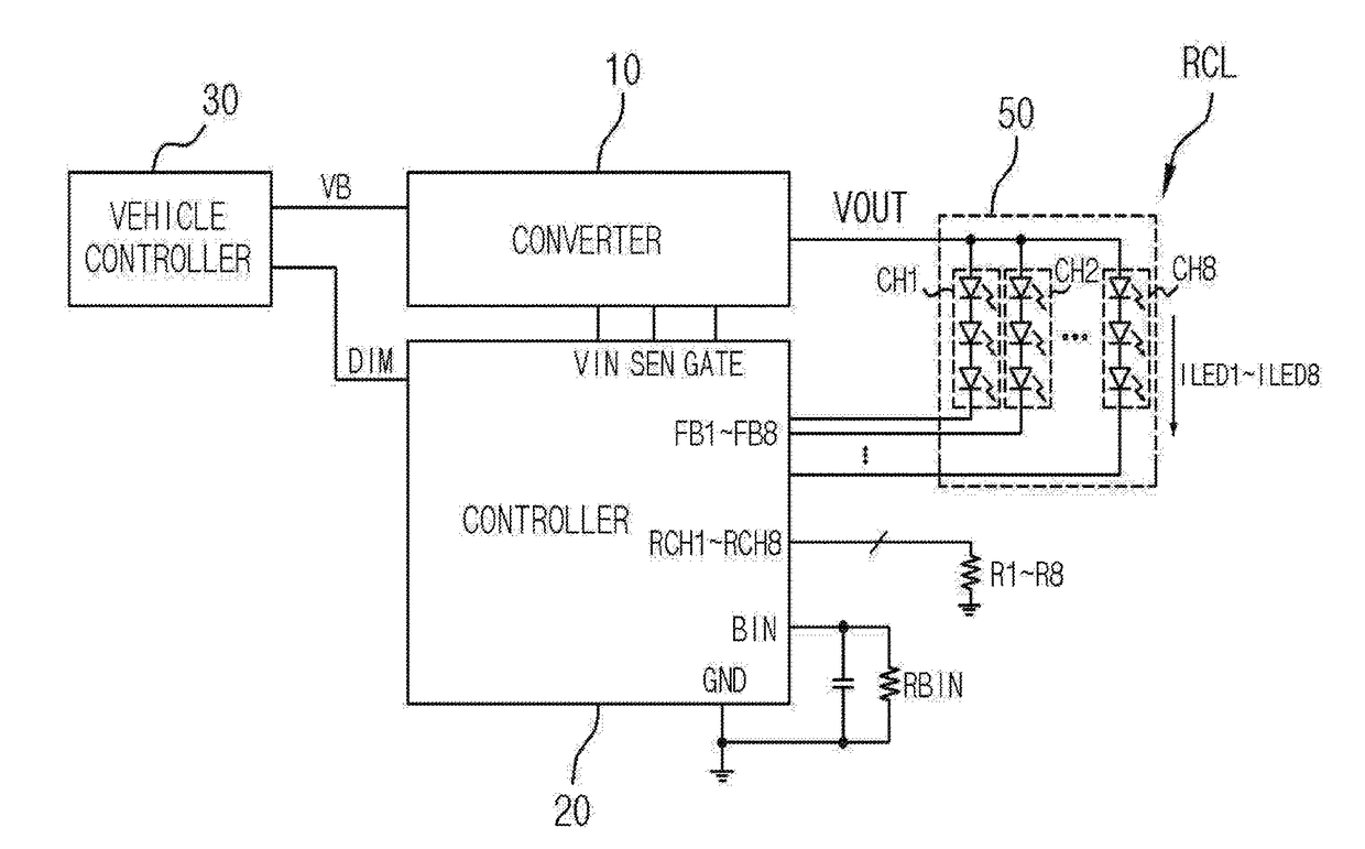
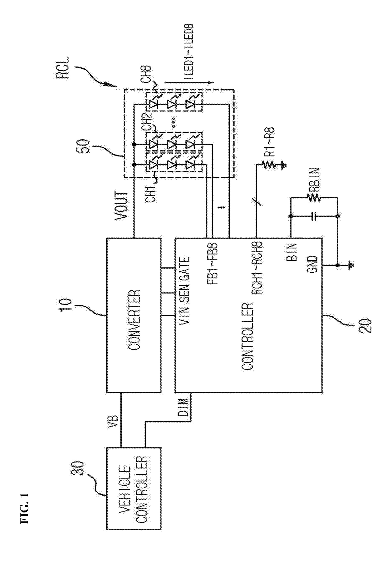
[0033]Various embodiments of the present invention disclose a lamp control device capable of reducing a power loss and EMI (Electro Magnetic Interference) which may occur while light emission of a lamp is controlled. For convenience of descripti...


PUM


Abstract

Disclosed is a lamp control device. The lamp control device may include: a lamp having an LED channel; a channel resistor corresponding to the LED channel; and a controller configured to boost a channel resistor voltage applied to the channel resistor, and retain a channel current of the LED channel as a target current, using the boosted channel resistor voltage.

Description

BACKGROUND1. Technical Field[0001]The present disclosure relates to a lamp control device, and more particularly, to a lamp control device capable of reducing a power loss and EMI (Electro Magnetic Interference).2. Related Art[0002]Recently, with the rapid development of high-brightness LEDs (Light Emitting Diode), a lamp having LEDs mounted therein has been developed. The lamp employing LEDs as a light source may be designed in various manners, and the number of LEDs used therein tends to increase.[0003]With the increase in number of LED channels, the number of channel resistors connected to the LED channels is also increasing. The channel resistors may generate heat when a channel current flows therethrough, and the heat generated by the channel resistors may increase a power loss.[0004]When the channel resistors are removed to reduce a power loss, noise may be introduced into a lamp control device. When the value of the channel resistor is reduced, a channel resistor voltage lowe...

Claims


Application Information

Patent Timeline
Patent Type & Authority Applications(United States)
IPC IPC(8): H05B33/08B60Q1/44B60Q1/34H05B44/00
CPCH05B33/0815H05B33/0845H05B33/0827B60Q1/44B60Q1/34H05B33/089F21V23/04H05B45/00H05B47/10H05B45/37H05B45/375H05B45/10H05B45/46
Inventor QU, WANYUANLEE, SE WONJEONG, BYEONG HOHONG, JU PYOLEE, JU HYUNKIM, SUNG HWANJIN, HAI FENGHA, JOO WANYOO, TAE YOUNG
Owner SILICON WORKS CO LTD
Why Eureka
Try Eureka