
Pivoting Piston Machine

a piston machine and rotating piston technology, applied in the direction of oscillating piston engines, lift valves, valve details, etc., can solve the problems of inability to adjust the opening and closing times of fresh gas inlet and exhaust gas outlet in a load-dependent and/or rotational-speed-dependent manner, and achieve faster and more uniform charging of the working chamber, increase the effect of outlay and speed

Inactive Publication Date: 2018-01-04
INNOWATT GMBH
View PDF2 Cites 0 Cited by
  • Summary
  • Abstract
  • Description
  • Claims
  • Application Information

AI Technical Summary

Benefits of technology

The pivoting piston machine described in this patent has a unique design that allows for faster and more uniform charging of the working chamber. By relocating the mouth of the inlet or outlet to the working chamber, the machine can distribute the working medium (fresh air) more evenly throughout. This results in a more uniform and efficient air conditioning system. Additionally, the patent suggests adjusting the angle of the cam relative to the toothed wheel to make the machine easier to construct. Overall, the technical effects of this new design are faster and more efficient air conditioning and easier construction.

Problems solved by technology

It could be considered to be a disadvantage of said pivoting piston machine that the admission and discharge of the working medium into and out of the working chamber takes place via a common mouth, in which the abovementioned closing element is arranged.
In this way, overlaps, that is to say temporally overlapping simultaneous opening-up of the outlet and of the inlet, such as are provided and have proven to be expedient in modern engine control regimes, are not possible.
It could be considered to be a disadvantage of this embodiment that the opening and closing times of fresh-gas inlet and exhaust gas outlet cannot be set in a load-dependent and / or rotational-speed-dependent manner.

Method used


Image

  • Pivoting Piston Machine
  • Pivoting Piston Machine
  • Pivoting Piston Machine

Examples


Embodiment Construction

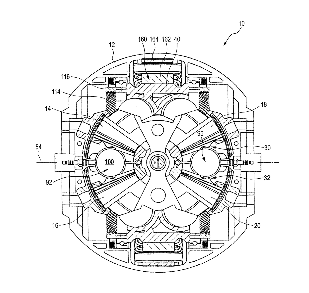
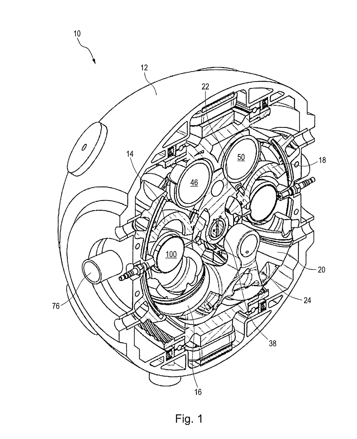
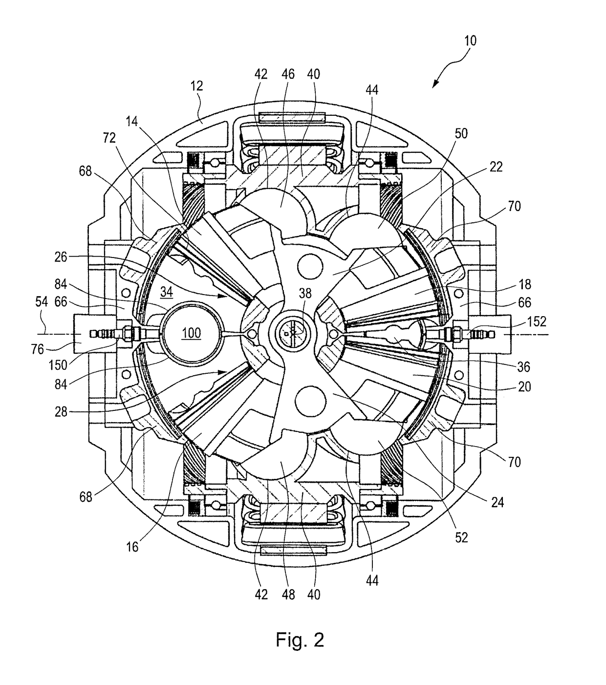
[0066]FIGS. 1 to 4 show a pivoting piston machine, denoted by the general reference label 10, in various views.

[0067]In the present exemplary embodiment, the pivoting piston machine 10 is designed for use as a combustion engine in combination with an electromotive part, and can thus be used as a hybrid apparatus for driving a motor vehicle. The pivoting piston machine 10 can, in slightly modified form, also be used as a generator or compressor.

[0068]With reference to FIGS. 1 to 4, the basic construction of the combustion-engine part of the pivoting piston machine 10 will firstly be described.

[0069]The pivoting piston machine 10 has a housing 12, of which one half is shown in FIG. 1. The housing 12 has, overall, the general shape of a sphere, which is correspondingly joined together from two hemispheres.

[0070]A first piston 14, a second piston 16, a third piston 18 and a fourth piston 20 are arranged in the housing 12.

[0071]The pistons 14, 16, 18 and 20 have a curved cylindrical shap...


PUM


Abstract

A pivoting piston machine includes a housing, a first piston and a second piston arranged in the housing, the first and second pistons being pivotable away from one another and toward one another about a pivot axis. The machine has a working chamber arranged between first and second piston. The working chamber increases and decreases in size in alternating fashion during pivoting of the first piston and of the second piston. The machine also has a inlet mouth for admission and discharge of the working medium. A closing element for closing and opening the inlet or the outlet has a valve disk interacting with a valve seat. Either the inlet mouth or the outlet mouth is arranged within the working chamber between the first end surface and the second end surface, and the valve seat and the valve disk are arranged at either the inlet mouth or the outlet mouth.

Description

CROSS-REFERENCES TO RELATED APPLICATIONS[0001]This application is a continuation of international patent application PCT / EP2016 / 055014, filed on Mar. 9, 2016 designating the U.S., which international patent application has been published in German language and claims priority from German patent application 10 2015 103 734.3, filed on Mar. 13, 2015. The entire contents of these priority applications are incorporated herein by reference.BACKGROUND OF THE INVENTION[0002]The invention relates to a pivoting piston machine, having a housing in which a first piston and a second piston are arranged, which are pivotable away from one another and toward one another about a pivot axis, wherein the first piston has a first end surface and the second piston has a second end surface, wherein a working chamber for a working medium is arranged between the first end surface and the second end surface, which working chamber increases and decreases in size in alternating fashion during the pivoting of...

Claims


Application Information

Patent Timeline
Patent Type & Authority Applications(United States)
IPC IPC(8): F02B53/06F01L1/04F01L1/344F02B53/14
CPCF02B53/06F01L1/04F01L1/344F02B53/14F01C9/002F01C21/002F01C21/18F01L1/02F01L1/026F01L1/12F01L3/00F01L3/20Y02T10/12
Inventor HUETTLIN, HERBERT
Owner INNOWATT GMBH
Learn More