Automated gas cooking system

Active Publication Date: 2018-01-11
W C BRADLEY CO
View PDF3 Cites 22 Cited by
  • Summary
  • Abstract
  • Description
  • Claims
  • Application Information

AI Technical Summary

Benefits of technology

The invention uses a single master control valve to manage the flow of gas fuel to multiple burners in a cooking chamber, reducing costs and improving reliability.

Problems solved by technology

However, in this control scenario, if at least one of the individual manual control valves for the multiple burners is not moved to, or is taken out of, the MCV activation position, and except for a possible time lag, the MCV preferably will not operate to control the rate of flow of the gas fuel to the burners.

Method used


Image

  • Automated gas cooking system
  • Automated gas cooking system
  • Automated gas cooking system

Examples


embodiment 100

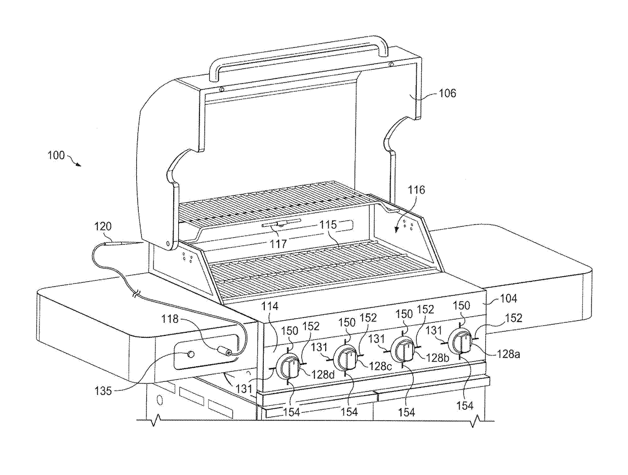
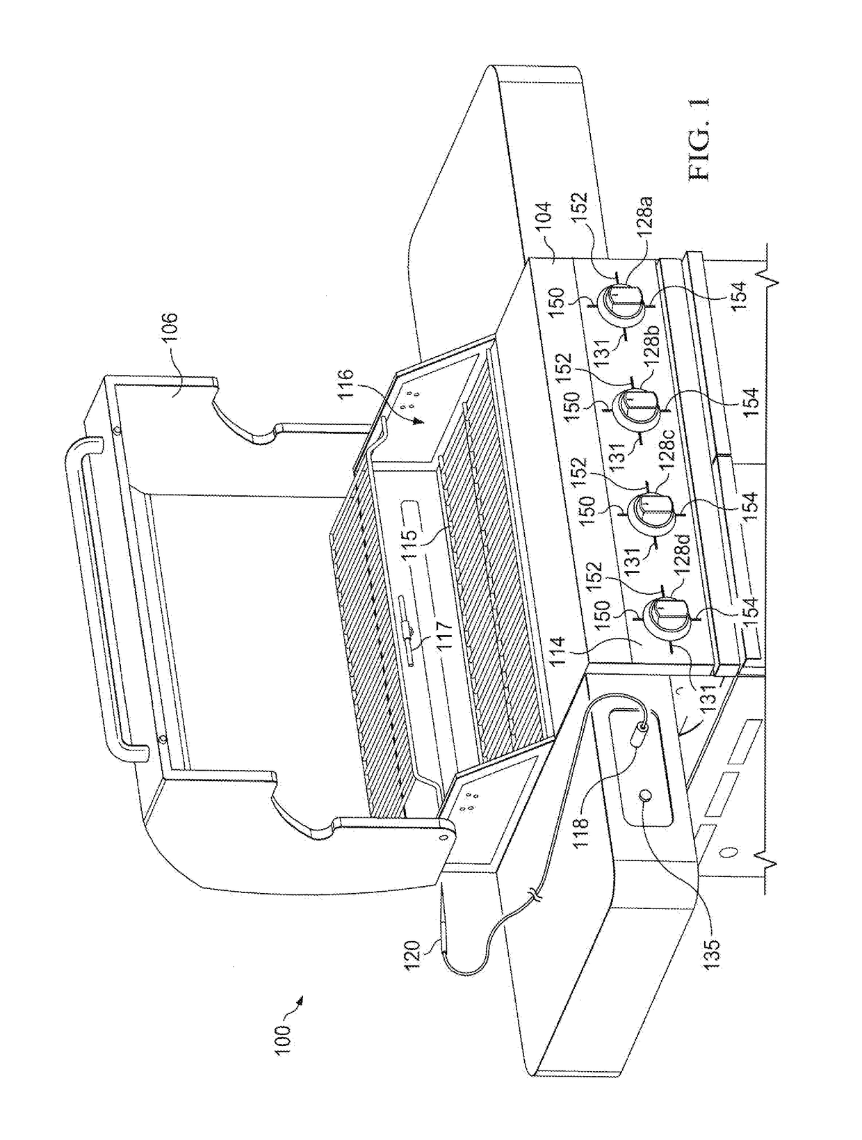
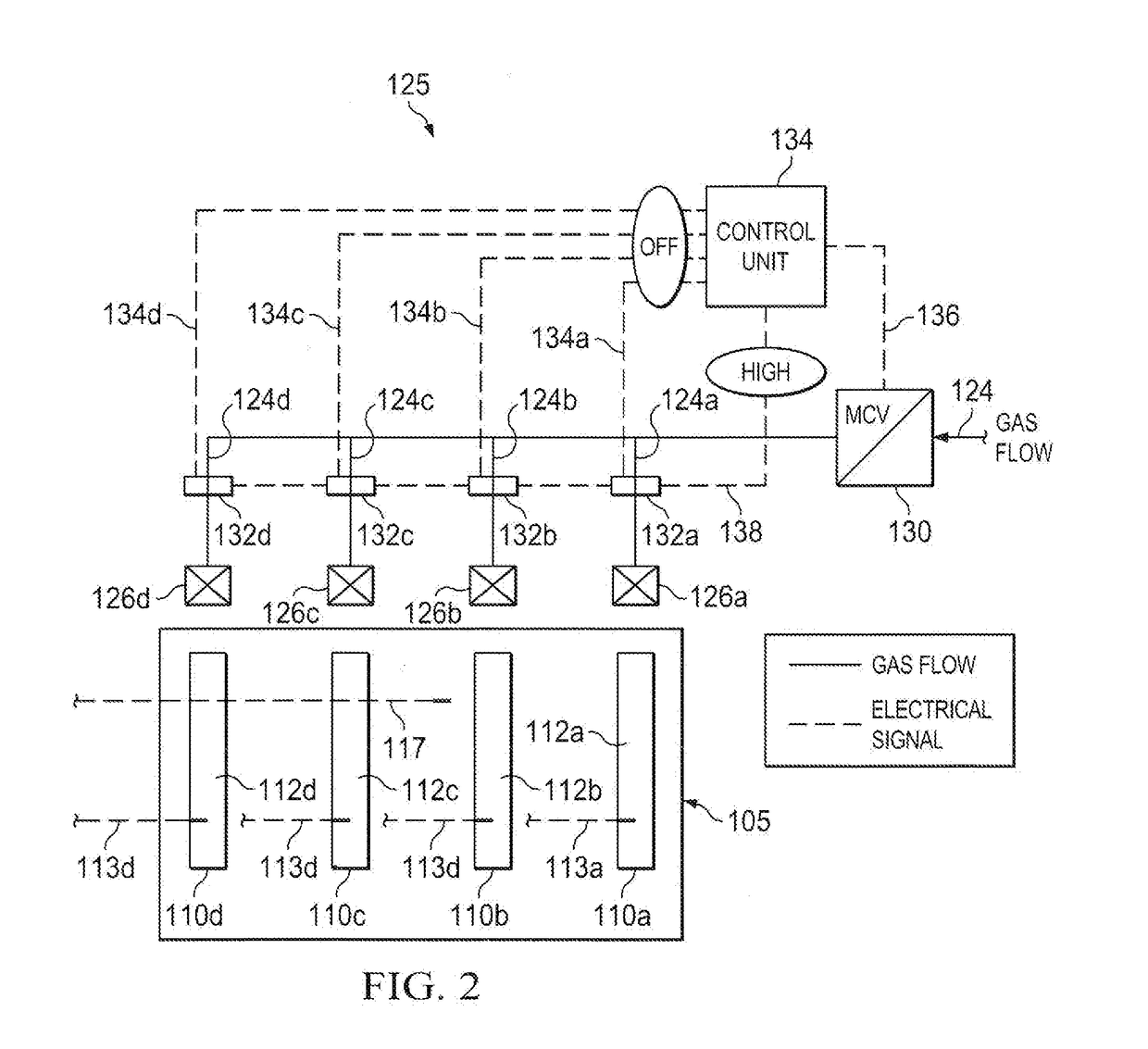
[0035]An embodiment 100 of the inventive outdoor gas cooking system is illustrated in FIGS. 1-4. The inventive cooker 100 comprises: a grill housing 104; a pivotable lid or other cover 106 for opening and closing the top opening 116 of the grill housing 104; a firebox 105 defined within the grill housing 104; multiple (i.e., a plurality of) individual burner assemblies 110a, 110b, 110c, 110d having burner elements 112a, 112b, 112c, 112d positioned within the firebox 105; one or more removable cooking grates or cooking grate assemblies 115 positioned above the burner elements 112a, 112b, 112c, 112d and preferably positioned at or near the top opening 116 of the grill housing 104; a front control panel 114; and an inventive automated gas fuel control system 125 or 225.

[0036]In addition, the inventive outdoor gas cooker 100 can also comprise: (a) burner flame monitors comprising thermocouples or other burner temperature probes 113a, 113b, 113c, 113d positioned at or in close proximity ...

embodiment 225

[0049]The above-mentioned alternative embodiment 225 of the fuel gas control system for the inventive cooker 100 is illustrated in FIG. 3. As with the control system 125, the control system 225 preferably comprises: (a) a Master Control Valve (MCV) 230 located in the main fuel supply conduit 124 upstream of the individual burner fuel supply inlets 124a, 124b, 124c, 124d and upstream of the individual manual control valves 126a, 126b, 126c, 126d; (b) individual valve position switches or other electronic valve position detectors 232a, 232b, 232c, 232d for detecting the operating positions of the individual burner control valves 126a, 126b, 126c, 126d; and (c) a control unit 234.

[0050]In contrast to the fuel gas control system 125, each of the valve position indicators 232a, 232b, 232c, and 232d of the alternative control system 225 has (a) its own individual electrical feed 238a, 238b, 238c, or 238d which extends from the control unit 234 to the valve position indicator 232a, 232b, 2...


PUM


Abstract

An outdoor gas cooking system having multiple burners in which, if the individual manual control valves for all of the burners are placed on a high heat setting or some other specified or recognized activation position, a single electronic master control valve can be activated to control the total gas fuel rate to all of the burners in the cooker based, for example, upon a cooking or operational control set point or upon a target flow rate equaling the sum of the design flow rates of all of the burners at the current operating set points of the manual valves.

Description

RELATED CASE[0001]This application claims the benefit of U.S. Provisional Patent Application Ser. No. 62 / 360,534 filed on Jul. 11, 2016 and incorporates said provisional application by reference into this document as if fully set out at this point.FIELD OF THE INVENTION[0002]The present invention relates to automated outdoor cookers. More particularly, the present invention relates to systems for automatically controlling fuel rates and operating procedures in outdoor grills and other outdoor cookers.BACKGROUND OF THE INVENTION[0003]In the past ten years, numerous cooking appliances have been developed which are equipped with on-board electronic displays and / or remote displays which provide textual or graphical information relative to the status of the food being cooked. In some cases, the temperature of the food being cooked is monitored over time and the temperature is displayed with respect to a target temperature set by the user. This information is displayed in many cases as a ...

Claims


Application Information

Patent Timeline
IPC IPC(8): A47J37/07H05B1/02
CPCA47J37/0786H05B1/0266A47J37/0713F23N1/002F24C3/126F23N2237/02F23N2239/04
Inventor BENNETT, CHRISGAFFORD, ALEX
Owner W C BRADLEY CO
Why Eureka
Try Eureka