Wind turbine blade vibration detection and radar calibration

a technology of radar calibration and vibration detection, which is applied in the field of radar calibration of wind turbine blades, can solve problems such as difficult maintenance of arrangemen

Active Publication Date: 2016-07-28
VESTAS WIND SYST AS
View PDF0 Cites 7 Cited by
  • Summary
  • Abstract
  • Description
  • Claims
  • Application Information

AI Technical Summary

Benefits of technology

[0014]Embodiments of the first aspect of the invention may provide a wind turbine, having a wind turbine tower and at least one rotatable blade, and further comprising a system for measuring rotor blade vibration of said wind turbine. The system comprises at least one Doppler radar unit operatively configured to emit and receive radar signals, the radar unit being mounted on the wind turbine tower at a position above the lowest position of the at least one blade, the radar unit being positioned so as to measure reflections of an emitted radar signal from the turbine blade. A processing unit is configured to receive measurement data from the radar unit and to determine, by analysis of Doppler shift in received radar signals relative to transmitted signals due to movement of the blade towards or away from the turbine tower, the velocity of the blade in the direction towards or away from the turbine tower. Using a radar unit to measure blade velocity allows a determination to be made of the vibrations occurring in the blade without needing an internal sensor in the blade. This reduces manufacturing and maintenance costs of the blades since sensors in the blades will not need to be replaced, and sensors positioned on the tower are easier to replace in the field.
[0017]The range profiles may include a plurality of range “bins”, each corresponding to a set or spread of ranges, the processing unit being configured to process the frequency components falling into the range bins corresponding to the position of the blade to obtain respective Doppler information relevant to the blade and not to other objects found at differing locations. Processing only those frequencies relevant to the blade, or to objects detected at the range of the blade, avoids unnecessary processing of unrelated detected objects.
[0018]Preferably the processing unit is configured to determine the velocity of the tower side (or suction side) and the opposite side (the pressure side) of the blade by identifying signals / reflections received from the respective blade sides. The processing unit may process the range profiles to obtain respective Doppler information for both the tower side and opposite side of the blade and compare the Doppler information for both blade sides to determine the velocity of each side of the blade in the direction towards or away from the turbine tower. Detecting the velocities of both major surfaces of the blade allows a comparison to be made to determine whether the structure of the blade itself is varying, his being the case if the velocity of one side is different to the velocity of the other.
[0020]A plurality of Doppler radar units may be used, each mounted on the turbine tower. A plurality of Doppler radar units may be arranged around the circumference of the wind turbine tower at a common height. Distributing radar units around the circumference allows readings to be taken at any yaw position. A plurality of Doppler radar units may alternatively or additionally be arranged linearly along the length of the tower between the centre of rotation of the blade and the lowest position of the blade, allowing for measurements of blade velocity at a plurality of points along the blade length to build up a velocity profile for the entire blade.

Problems solved by technology

Such arrangements are difficult to maintain because of the difficulty in accessing the sensors, and the difficulty in providing communication paths for the sensors to return data to a central processing unit.

Method used


Image

  • Wind turbine blade vibration detection and radar calibration
  • Wind turbine blade vibration detection and radar calibration
  • Wind turbine blade vibration detection and radar calibration

Examples


Embodiment Construction

[0052]Embodiments according to a first aspect of the present invention will now be described.

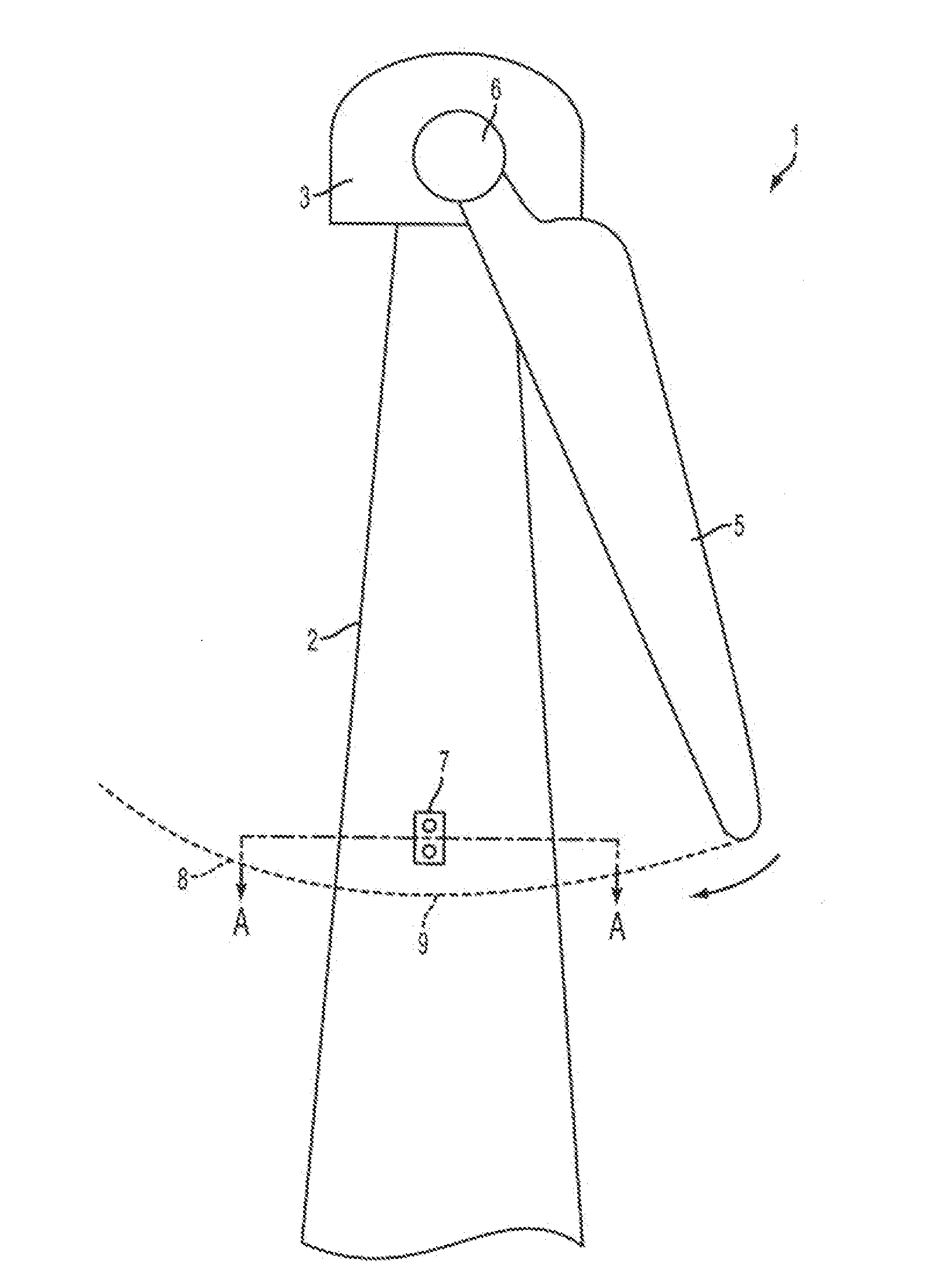
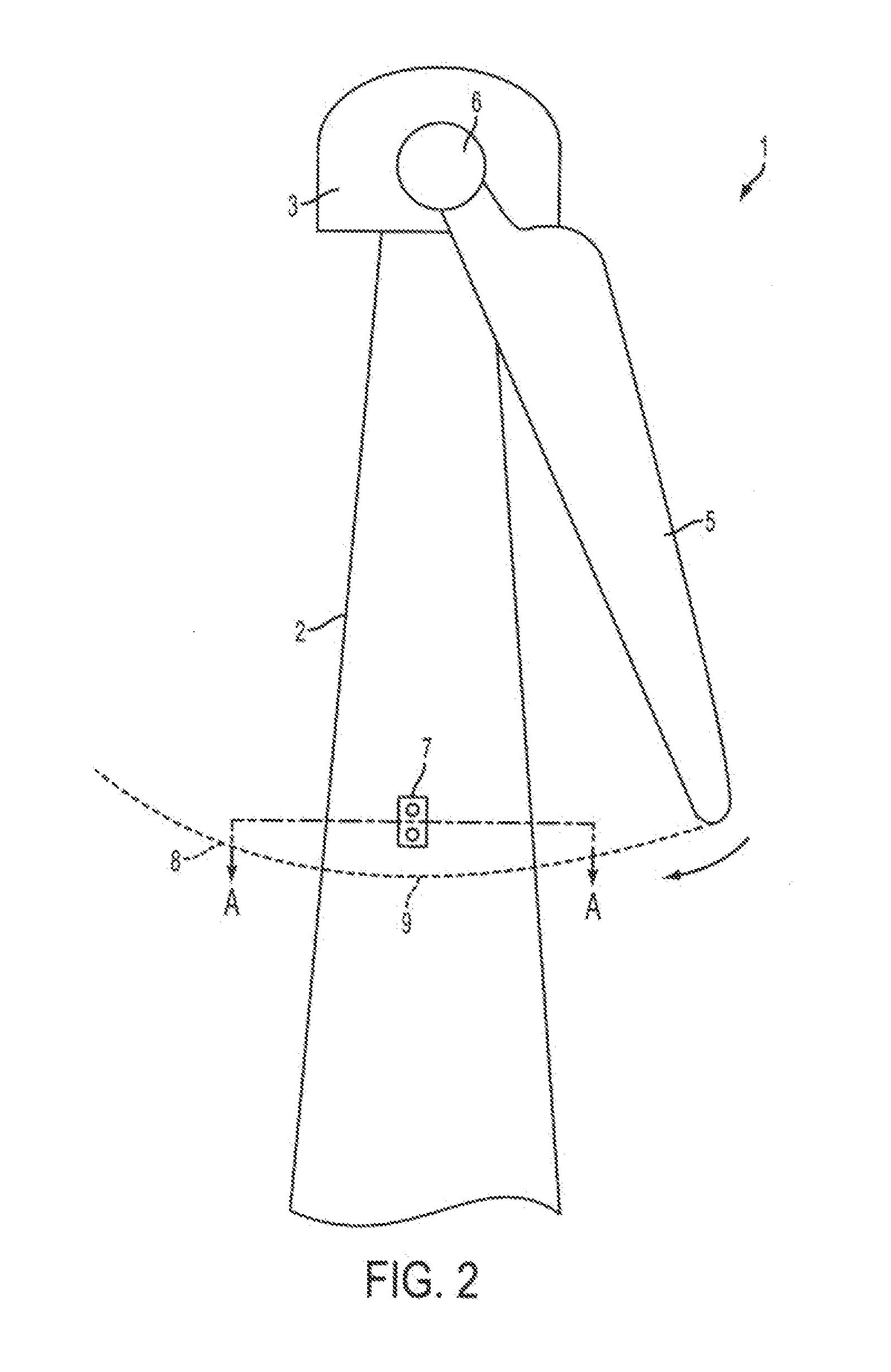
[0053]FIG. 2 shows a schematic illustration of a wind turbine incorporating a radar unit 7. The wind turbine is shown as having only a single blade for illustration purposes only. It will be appreciated that a wind turbine will usually have more blades, and typically will have three blades. As wind is incident on the blade it causes a rotation in the direction indicated by the arrow in the figure. The blade traces out a circular path 8 and reaches its lowest point 9 relative to the base of the turbine when the major or lengthwise axis of the blade is vertical; that is, the blade reaches its lowest point in its rotation when its major axis coincides with the main / vertical axis of the tower 2.

[0054]Fixed to the tower is a radar unit comprising an emitter and receiver. The radar unit is positioned above the lowest point 9 at which the blade passes such that radar signals emitted from the radar ...


PUM


Abstract

A wind turbine is provided, having a wind turbine tower and at least one rotatable blade, and further comprising a system for measuring rotor blade vibration of said wind turbine. The system comprises at least one Doppler radar unit operatively configured to emit and receive radar signals, the radar unit being mounted on the wind turbine tower at a position above the lowest position of the at least one blade, the radar unit being positioned so as to measure reflections of an emitted radar signal from the turbine blade. A processing unit is configured to receive measurement data from the radar unit and to determine, by analysis of Doppler shift in received radar signals relative to transmitted signals due to movement of the blade towards or away from the turbine tower, the velocity of the blade in the direction towards or away from the turbine tower. Using a radar unit to measure blade velocity allows a determination to be made of the vibrations occurring in the blade without needing an internal sensor in the blade. This reduces manufacturing and maintenance costs of the blades since sensors in the blades will not need to be replaced, and sensors positioned on the tower are easier to replace in the field.

Description

CROSS-REFERENCE TO RELATED APPLICATIONS[0001]This application is a continuation of U.S. application Ser. No. 14 / 410,812, filed Dec. 23, 2014, which is a National Stage application of PCT / DK2013 / 050211, filed Jun. 25, 2013, which claims benefit of U.S. provisional patent application Ser. No. 61 / 664,175, filed Jun. 26, 2012, and foreign priority to Danish application serial number PA 2012 70363, filed Jun. 26, 2012, all of which are herein incorporated by reference in their entirety.FIELD OF THE INVENTION[0002]A first aspect of the present invention relates to a system or apparatus and corresponding method for detection of vibrations of wind turbine rotor blades.[0003]A second aspect of the present invention relates to a method for performing diagnostics and calibration on an array antenna.BACKGROUND OF THE INVENTION[0004]FIG. 1 illustrates a typical wind turbine 1. The wind turbine comprises a wind turbine tower 2 on which a wind turbine nacelle 3 is mounted. A wind turbine rotor 4 c...

Claims


Application Information

Patent Timeline
Patent Type & Authority Applications(United States)
IPC IPC(8): F03D17/00G01S7/40G01S13/58F03D1/06
CPCF03D17/00G01S13/583G01S7/4004F03D1/0675F03D7/0296F05B2240/912F05B2270/17F05B2270/33F05B2270/334F05B2270/805G01S13/505G01S13/582G01S13/584G01S13/589G01S13/64G01S13/87G01S13/88Y02B10/30Y02E10/72Y02E10/728Y02P70/50F03D7/04
Inventor VANGEN, KNUTMEUM, ERICPLEYM, JAN
Owner VESTAS WIND SYST AS
Why Eureka
Try Eureka