
IP telephone system

a telephone system and telephone technology, applied in the field of communication devices, can solve the problems of component failure increase the manufacturing part count and ultimately the manufacturing cost of an ip phone, etc., to reduce manufacturing and maintenance costs, minimize the problem of return loss, and constant input impedance

Inactive Publication Date: 2009-03-17
AVAGO TECH INT SALES PTE LTD
View PDF7 Cites 4 Cited by
  • Summary
  • Abstract
  • Description
  • Claims
  • Application Information

AI Technical Summary

Benefits of technology

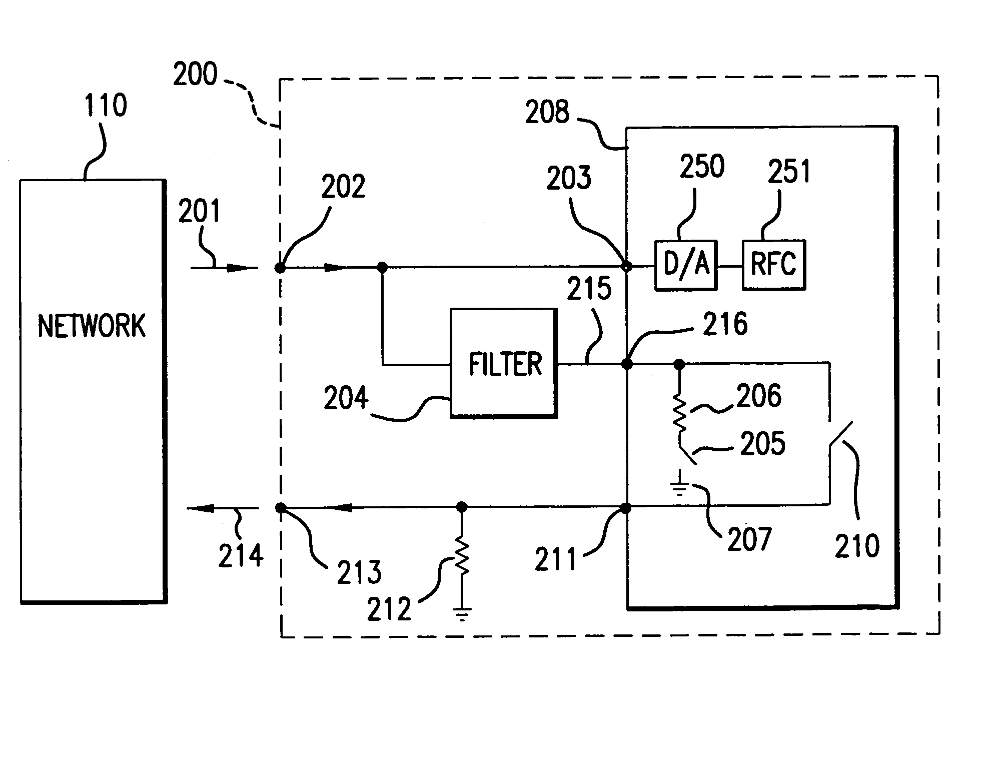
[0013]The filter in the present invention filters out unwanted frequency signals by passing only desired frequency signals through the filter, and terminating undesired signals. The filter can remain connected to the system during both the discovery mode and the normal operation mode, because it has a substantially constant input impedance. The filter is configured to maintain a constant impedance through the entire filter for substantially all input frequencies. The filter may have several embodiments depending on the type of frequency signals that are being processed. A single ended filter may be one of the embodiments, where a plurality of poles are connected in series. The poles comprise an inductor, a capacitor and a resistor connected to the ground. Another embodiment may be a differential filter, where another inductor connects the poles. Yet another embodiment may be a band pass filter having a low pass circuit with a high pass circuit connected to it. The filter minimizes a return loss problem that is common in the conventional filters.
[0014]External relays are eliminated by leaving the filter connected to the relay and to the substrate. This reduces manufacturing and maintenance costs that are associated with these external relays that are used in conventional IP telephone systems.

Problems solved by technology

The continual opening and closing of the relay creates wear and tear of the relay components as the conventional IP phone switches between the discovery and normal modes, eventually causing component failure.
Additionally, the conventional relay is not integrated with the computer or the filter, which increases the manufacturing part count and ultimately the manufacturing cost of an IP Phone.
The termination circuit is a separate off-chip device, which increases the manufacturing part count and ultimately the manufacturing cost of an IP Phone.
Input frequencies that are outside of the filter passband are substantially reflected, which can produce an undesired high return loss.
Also, conventional filters are highly sensitive to variations in the filter components and in the variation of components that are connected to the filter.

Method used


Image

  • IP telephone system
  • IP telephone system
  • IP telephone system

Examples


Embodiment Construction

Conventional Internet Protocol Telephone

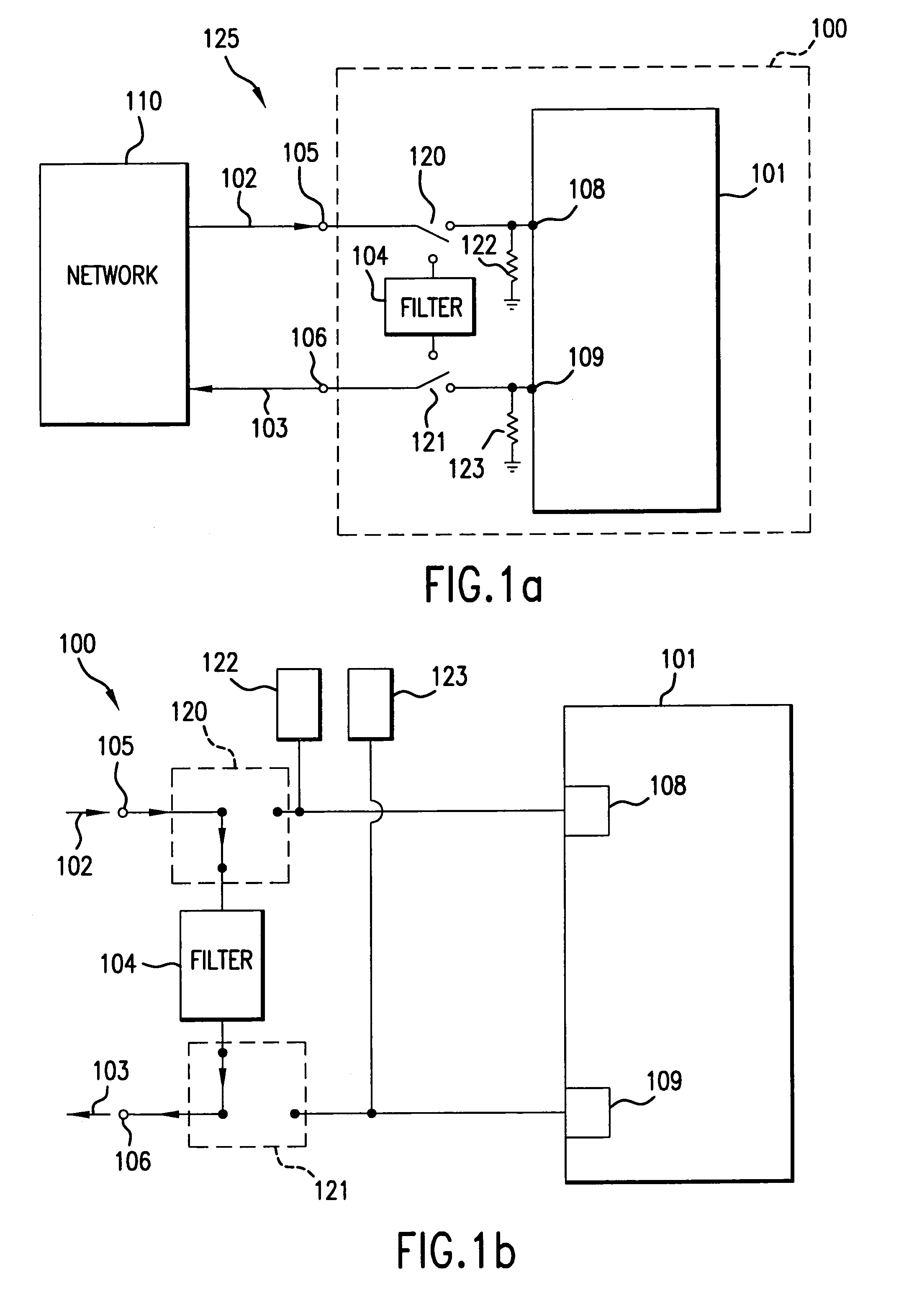
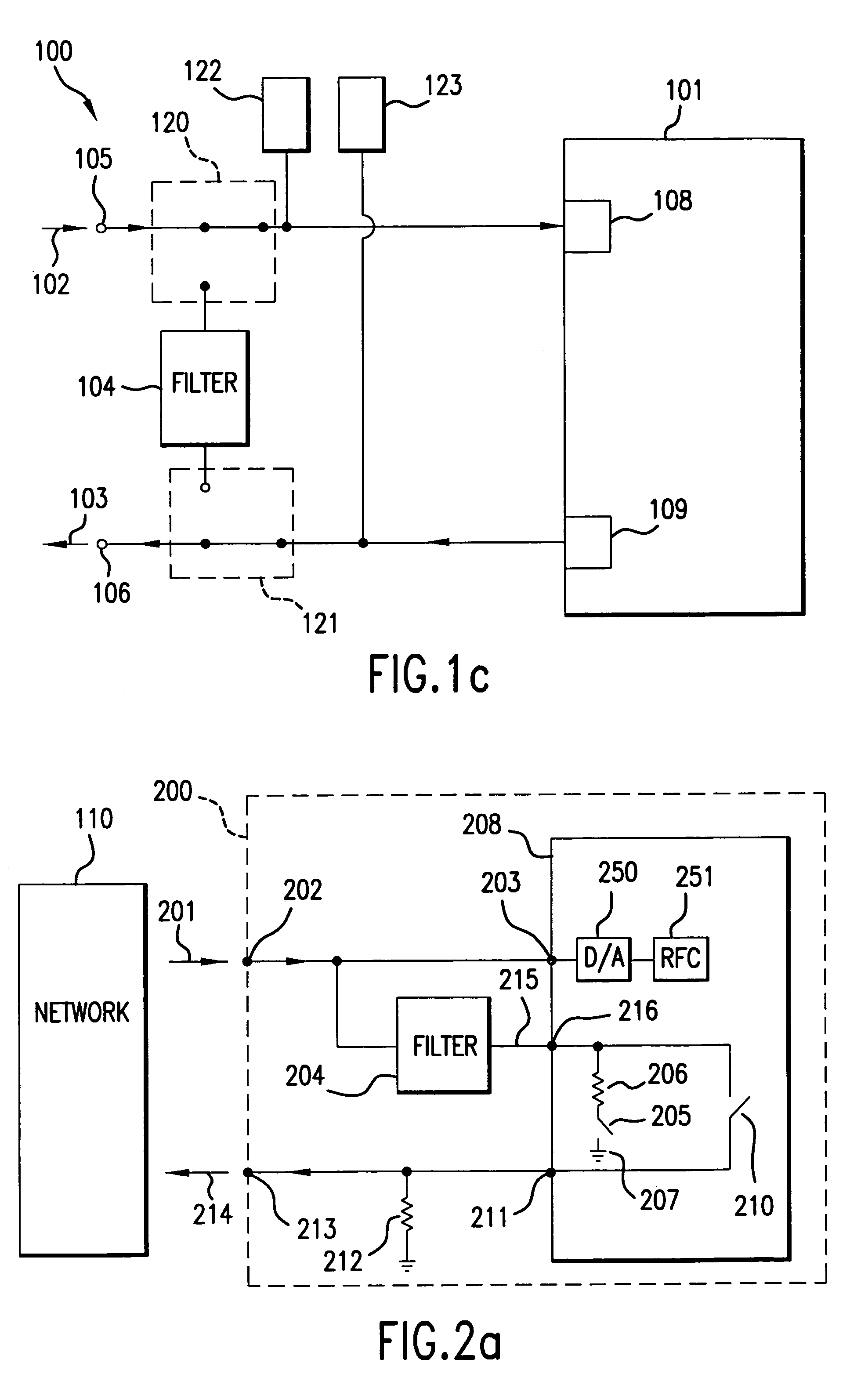
[0040]FIG. 1a illustrates a conventional IP telephone system 125 having a data network 110 and a conventional IP telephone 100. The data network 110 can be the publically available Internet, or another type of public or private network. The IP telephone 100 receives signals 102 from the network 110 at an input terminal 105, and transmits signals 103 to the data network 110 at the output terminal 106. In embodiments, the signals 102 and 103 carry voice communications using Internet Protocol.

[0041]The IP telephone 100 includes a filter 104, relays 120 and 121, and a physical layer 101 that is part of a computer chip (not shown) or other type of integrated circuit. The computer chip processes voice and data signals that are sent to and received from the data network 110. The relay 120 connects the input terminal 105 to either the filter 104 or an input terminal 108 of the physical layer 101. Likewise, the relay 121 connects the output terminal 10...


PUM


Abstract

An Internet Protocol (IP) telephone has a constant impedance filter that is capable of being continuously attached to the physical layer of a computer chip in the IP telephone. The constant impedance filter is located outside the physical layer and is connected to a relay on the physical layer. The relay is configured using native FET devices, which are normally conductive without a supply voltage. Therefore, the relay is capable of operating during the discovery mode of IP telephone operation, where no power is applied to the substrate. Rectifier circuits rectify an incoming signal during discovery mode, and apply the rectified signal to the gate of the relay to improve conductivity of the relay. This allows for faster detection of the IP telephone during discovery mode. During normal operation mode, voltage is applied to the physical layer, and the relay is opened by grounding the native devices. Also, during the normal operation mode, any signal coming from the constant impedance filter is terminated in a switchable termination resistor that is also disposed on the physical layer.

Description

CROSS-REFERENCE TO RELATED APPLICATIONS[0001]This application is a continuation-in-part of U.S. application Ser. No. 09 / 986,752 filed on Nov. 9, 2001, which claims the benefit of U.S. Provisional Application No. 60 / 246,991, filed on Nov. 9, 2000, both of which are incorporated by reference herein in their entireties.[0002]This application also claims benefit of U.S. Provisional Application No. 60 / 258,777, filed on Dec. 28, 2000, which is incorporated by reference herein in its entirety.BACKGROUND OF THE INVENTION[0003]1. Field of the Invention[0004]The present invention is related to a communications device. More specifically, the present invention is related to an IP telephone having an on-chip native device relay, and an on-chip filter termination for a constant impedance filter that is located off-chip.[0005]2. Background Art[0006]In addition to data communications, the Internet can also be used to carry voice telephony. One conventional system that carries voice communications o...

Claims


Application Information

Patent Timeline
Patent Type & Authority Patents(United States)
IPC IPC(8): H04M7/04H03H7/06H03H7/075H04M1/253
CPCH03H7/06H03H7/075H03H7/1758H03H7/38H04M1/2535H03H7/425Y10S379/90
Inventor FALLAHI, SIAVASHCHU, LIN ABLE
Owner AVAGO TECH INT SALES PTE LTD
Learn More