Clot retrieval system

Active Publication Date: 2018-01-11
LEGACY VENTURES
View PDF0 Cites 3 Cited by
  • Summary
  • Abstract
  • Description
  • Claims
  • Application Information

AI Technical Summary

Benefits of technology

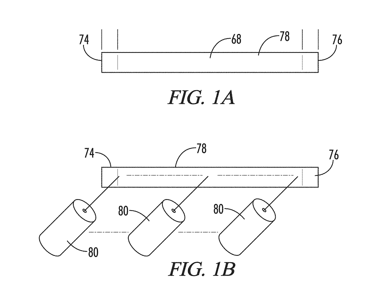
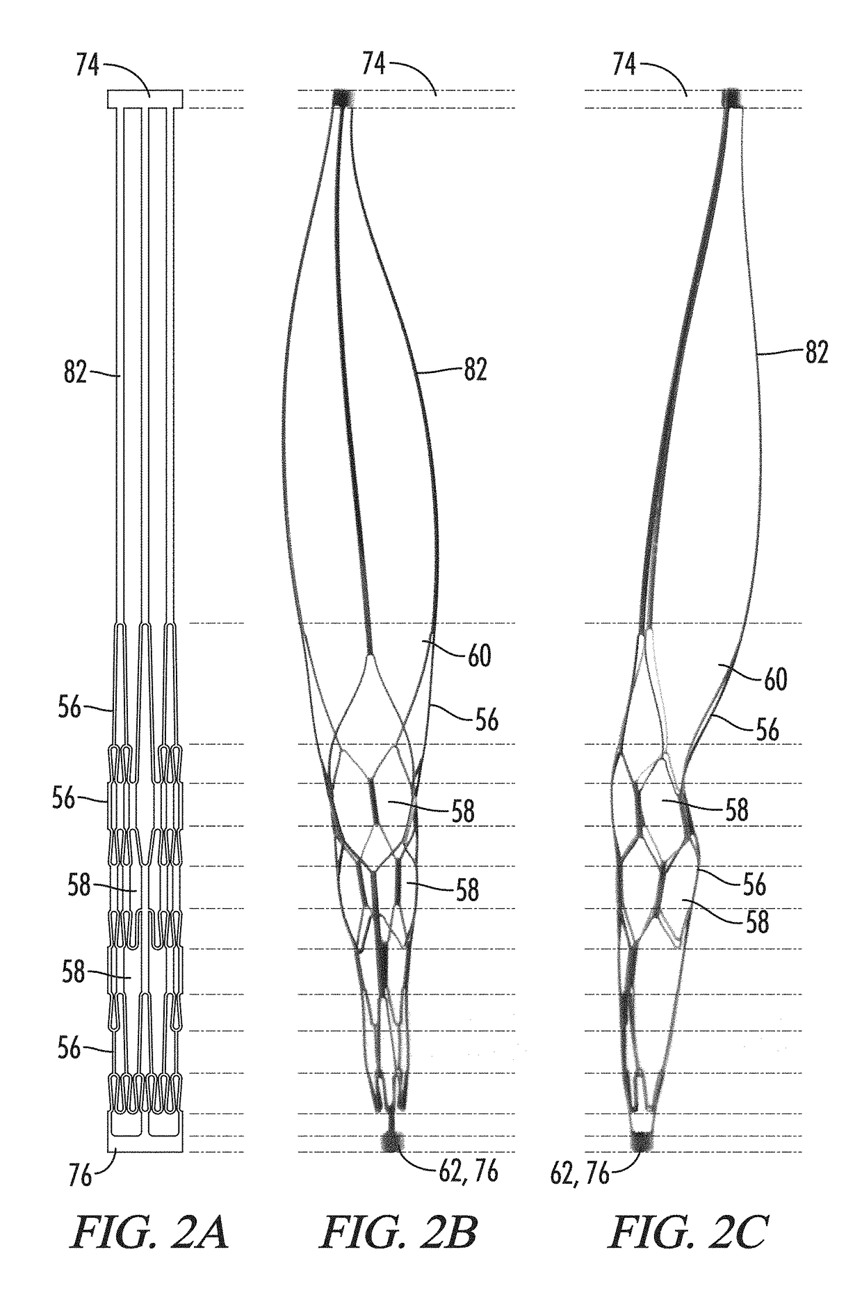
[0088]The present disclosure also provides additional modular, easy-to-manufacture platform of systems for retrieving hard clots and other objects in animal lumens. In some embodiments, the system includes a proximal tube, a distal tube, and a plurality of memory metal strips between the proximal and distal tubes. The plurality of memory metal strips form a wide range of basket designs. Preferably, the proximal tube, memory metal strips, and distal tube are derived from a standard, off-the-shelf single tube of memory metal (e.g., a memory metal alloy such as nitinol), with the proximal tube and distal tube having the same inner diameter and outer diameter as the native tube from which they were derived and with the basket formed by cutting the middle portion of the native tube and expanding and shape-setting this cut portion. Preferably, the proximal tube and distal tube have an outer diameter that is from about 0.02 inches to about 0.03 inches (e.g., about 0.027 inches) so that the device fits inside a standard microcatheter and an inner diameter that is from about 0.01 inches to about 0.02 inches. Preferably, there are no welded or soldered parts between the proximal tube and distal tube, which makes the system easy and cheap to reliably manufacture. The system also includes one or more catheters for deploying t

Problems solved by technology

Needless to say, when a blood clot creates such a blockage, time in removing the clot is critical.
The removal of intracranial obstructions is limited by several factors, such as the distance of the intracranial obstruction from the femoral access site, the tortuosity (twists and turns in the artery as it enters the base of the skull) of the cervical and proximal intracranial vasculature, the small size of the vessels and the extremely thin walls of intracranial vessels, which lack a significant muscular layer.
The device should be retrievable without the need for proximal occlusion of the vessel, which carries risk of further ischemia and risk of vessel injury.
Currently available intravascular thrombus and foreign body removal devices lack several of these features.
All the devices are ineffectual at removing organized hard thrombus that embolize to th

Method used


Image

  • Clot retrieval system
  • Clot retrieval system
  • Clot retrieval system

Examples


Embodiment Construction

[0457]With reference to FIGS. 1-10, the present disclosure provides a deployable system, generally designated by the numeral 10, for removing an obstruction such as a blood clot 12 or other object from a blood vessel 14 or other interior lumen of an animal. In addition to a blood clot 12, the obstruction may be, for example, extruded coils during aneurysm treatment, intravascular embolic material such as onyx or other obstructions requiring mechanical intravascular removal from small distal vessels. In the drawings, not all reference numbers are included in each drawing for the sake of clarity.

[0458]Referring further to FIGS. 1-10, the deployable system 10 includes a pull wire 16 that has a proximal end (not shown) and a distal end 20. Optionally, the diameter of the pull wire is between about 0.008 inches and about 0.051 inches. Preferably, the pull wire 16 is comprised of a biocompatible metallic material.

[0459]The system 10 further includes a distal body 22, which is attached to ...


PUM


Abstract

Catheter-delivered endovascular medical devices are described. The devices may include a pull wire attached to a distal body. The distal body may be formed of a distal body outer body comprising a basket comprised of a plurality of cells defined by a plurality of basket strips and a distal body inner body located in the interior of the distal body outer body and comprising a plurality of distal braided mesh openings formed by a plurality of woven linear strands. The distal braided mesh openings may be smaller than the cells when the device is in the relaxed state. Methods of using and making the devices are also described.

Description

RELATED APPLICATIONS[0001]This application is a continuation-in-part of U.S. patent application Ser. No. 15 / 629,703, filed Jun. 21, 2017 and entitled “CLOT RETRIEVAL SYSTEM”, which is a continuation-in-part of U.S. patent application Ser. No. 15 / 611,762, filed Jun. 1, 2017 and entitled “CLOT RETRIEVAL SYSTEM”, which is a continuation-in-part of U.S. patent application Ser. No. 15 / 610,209, filed May 31, 2017 and entitled “CLOT RETRIEVAL SYSTEM”, which is a continuation-in-part of U.S. patent application Ser. No. 15 / 449,901 filed Mar. 3, 2017 and entitled “CLOT RETRIEVAL SYSTEM”, which is a continuation-in-part of U.S. patent application Ser. No. 15 / 417,505, filed Jan. 27, 2017 and entitled “CLOT RETRIEVAL SYSTEM”, which is a continuation-in-part of U.S. patent application Ser. No. 15 / 374,307, filed Dec. 9, 2016 and entitled CATHETER-DELIVERED ENDOVASCULAR DEVICES, which is a continuation-in-part of U.S. patent application Ser. No. 15 / 158,137, filed May 18, 2016 and entitled METHOD OF...

Claims


Application Information

Patent Timeline
IPC IPC(8): A61B17/221A61B17/00A61M25/01A61B6/12
CPCA61B2017/00323A61B2017/00778A61B2017/00867A61B2017/2212A61B2090/3966A61B6/12A61M25/0108A61B17/00234A61B17/221A61B2017/00526A61B2017/00893A61B2017/22079A61B2017/22084
Inventor ULM, III, ARTHUR JOHN
Owner LEGACY VENTURES
Why Eureka
Try Eureka