Catheter-delivered endovascualar devices

a technology of endovascual valve and catheter, which is applied in the field of deployment systems, can solve the problems of limited intracranial obstruction removal, risk of further ischemia, and risk of vessel injury, and achieve the effect of easy and cheap manufacturing

Active Publication Date: 2017-05-25
LEGACY VENTURES
View PDF1 Cites 13 Cited by
  • Summary
  • Abstract
  • Description
  • Claims
  • Application Information

AI Technical Summary

Benefits of technology

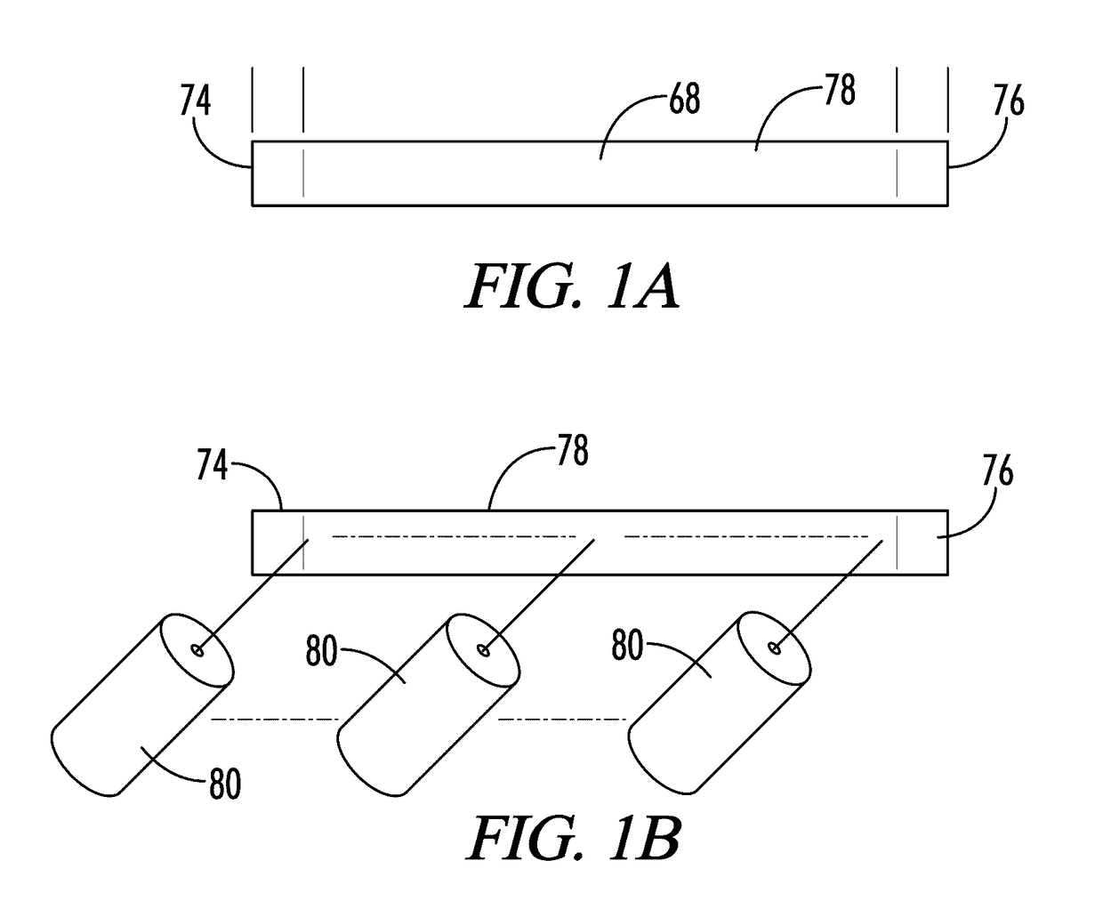
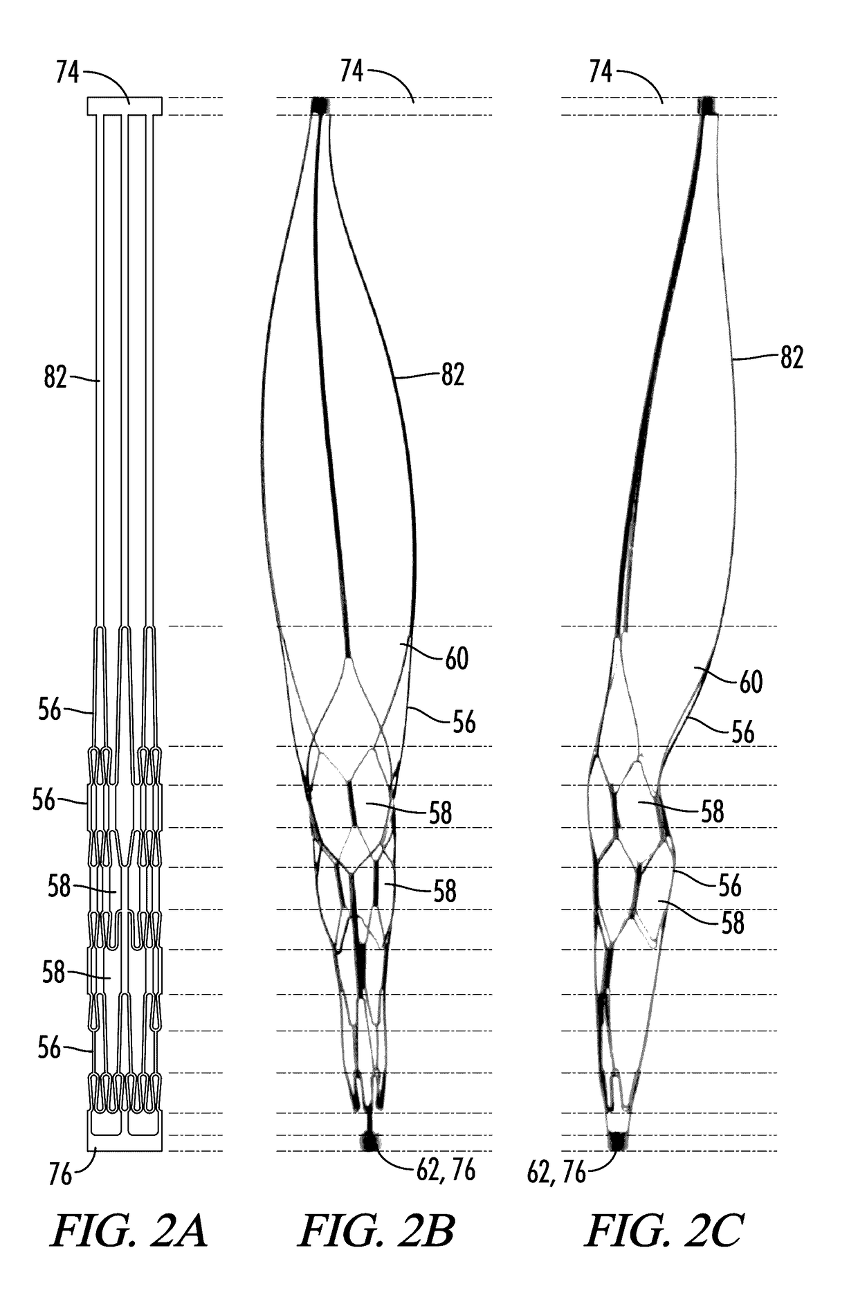
[0070]The present disclosure also provides additional modular, easy-to-manufacture platform of systems for retrieving hard clots and other objects in animal lumens. In some embodiments, the system includes a proximal tube, a distal tube, and a plurality of memory metal strips between the proximal and distal tubes. The plurality of memory metal strips form a wide range of basket designs. Preferably, the proximal tube, memory metal strips, and distal tube are derived from a standard, off-the-shelf single tube of memory metal (e.g., a memory metal alloy such as nitinol), with the proximal tube and distal tube having the same inner diameter and outer diameter as the native tube from which they were derived and with the basket formed by cutting the middle portion of the native tube and expanding and shape-setting this cut portion. Preferably, the proximal tube and distal tube have an outer diameter that is from about 0.02 inches to about 0.03 inches (e.g., about 0.027 inches) so that the device fits inside a standard microcatheter and an inner diameter that is from about 0.01 inches to about 0.02 inches. Preferably, there are no welded or soldered parts between the proximal tube and distal tube, which makes the system easy and cheap to reliably manufacture. The system also includes one or more catheters for deploying the system, a pull wire that passes through the hollow interior of the proximal tube, and a coaxial tube. Preferably, the system includes two catheters—a guide catheter and a microcatheter. The coaxial tube envelopes the pull wire, is slideable along at least a segment of the pull wire, and is attached to the proximal hub / junction. The coaxial tube allows a user to move the proximal hub / junction toward and away from the distal hub / junction while keeping the distal hub / junction stationary. Movement of the proximal hub / junction toward and away from the distal hub / junction causes conformational changes in the basket, including (depending on the basket design and the location of the proximal tube), collapsing the basket, expanding the basket, strengthening the basket, and moving the basket around the clot. The plurality of memory metal strips attached to the proximal hub / junction include a plurality of proximal tether memory metal strips, which have a proximal end attached to the distal end of the proximal tube. The length and thickness of the proximal tether memory metal strips vary in the different embodiments described herein, which allows the surgical user to select from the various embodiments in the platform based on the features needed for the particular operation (e.g., vessel anatomy and hardness of the clot).

Problems solved by technology

Needless to say, when a blood clot creates such a blockage, time in removing the clot is critical.
The removal of intracranial obstructions is limited by several factors, such as the distance of the intracranial obstruction from the femoral access site, the tortuosity (twists and turns in the artery as it enters the base of the skull) of the cervical and proximal intracranial vasculature, the small size of the vessels and the extremely thin walls of intracranial vessels, which lack a significant muscular layer.
The device should be retrievable without the need for proximal occlusion of the vessel, which carries risk of further ischemia and risk of vessel injury.
Currently available intravascular thrombus and foreign body removal devices lack several of these features.
All the devices are ineffectual at removing organized hard thrombus that embolize to the brain from the heart and from atherosclerotic proximal vessels.
Most of the time, the device fails to dislodge the thrombus from the wall of the vessel and often, even when successfully dislodging the thrombus, the thrombus embolizes into another or the same vessel due to the open ended nature of the device.
The device is ineffective at removing hard, organized thrombus which has embolized from the heart, cholesterol plaque from proximal feeding arteries and other foreign bodies.
Again, these devices are ineffectual at treating hard thrombus.
Upon retrieval of the devices, the clot remains or is broken up into several pieces which embolize to vessels further along the vessel.
However, it is also desirable to allow the devices to fit into a small catheter (called a microcatheter), which creates issues if the proximal and distal ends remain on the device.

Method used


Image

  • Catheter-delivered endovascualar devices
  • Catheter-delivered endovascualar devices
  • Catheter-delivered endovascualar devices

Examples


Embodiment Construction

[0273]With reference to FIGS. 1-10, the present disclosure provides a deployable system, generally designated by the numeral 10, for removing an obstruction such as a blood clot 12 or other object from a blood vessel 14 or other interior lumen of an animal. In addition to a blood clot 12, the obstruction may be, for example, extruded coils during aneurysm treatment, intravascular embolic material such as onyx or other obstructions requiring mechanical intravascular removal from small distal vessels. In the drawings, not all reference numbers are included in each drawing for the sake of clarity.

[0274]Referring further to FIGS. 1-10, the deployable system 10 includes a pull wire 16 that has a proximal end (not shown) and a distal end 20. Optionally, the diameter of the pull wire is between about 0.008 inches and about 0.051 inches. Preferably, the pull wire 16 is comprised of a biocompatible metallic material.

[0275]The system 10 further includes a distal body 22, which is attached to ...


PUM

PropertyMeasurementUnit
angleaaaaaaaaaa
angleaaaaaaaaaa
inner diametersaaaaaaaaaa

Abstract

Catheter-delivered endovascular medical devices are described. The devices may include a pull wire attached to a deployable dual basket system. The deployable dual basket system may include a proximal basket and a distal basket that are connected by basket connector tether memory metal strips that rotate/twist relative to the longitudinal axes of the basket and form flex points of the system. The proximal basket and the distal basket may be comprised of a plurality of cells and the proximal basket may taper at its proximal end and the distal basket may be tapered at its distal end. Methods of using and making the devices are also described.

Description

RELATED APPLICATIONS[0001]This application is a continuation-in-part of U.S. patent application Ser. No. 15 / 158,137, filed May 18, 2016 and entitled METHOD OF MANUFACTURING A CATHETER-DELIVERED MEDICAL DEVICE FROM A TUBE, which is a continuation-in-part of U.S. patent application Ser. No. 14 / 794,783, filed Jul. 8, 2015 and entitled “CLOT RETRIEVAL SYSTEM”), which is continuation-in-part of U.S. patent application Ser. No. 14 / 558,712 (now U.S. Pat. No. 9,155,552), filed Dec. 2, 2014 and entitled “CLOT RETRIEVAL SYSTEM, which is a continuation of U.S. patent application Ser. No. 14 / 558,705 (now U.S. Pat. No. 9,173,668), filed Dec. 2, 2014 and entitled “CLOT RETRIEVAL SYSTEM”, which is a continuation-in-part of U.S. patent application Ser. No. 14 / 147,491 (now U.S. Pat. No. 8,900,265), entitled “CLOT RETRIEVAL SYSTEM” and filed Jan. 3, 2014. U.S. patent application Ser. No. 14 / 558,705 further claims priority under 35 U.S.C. §119 to U.S. Provisional Patent Application Ser. No. 61 / 994,934...

Claims


Application Information

Patent Timeline
Patent Type & Authority Applications(United States)
IPC IPC(8): A61F2/01
CPCA61F2/013A61F2002/016A61F2002/011A61B17/221A61B2017/00477A61B2017/00526A61B2017/2212A61B2017/2215A61M5/007A61M2025/0042A61B2090/3966A61F2/012B23K26/38B23K26/40B23K2101/06A61B2017/00867A61B2017/22079A61M25/0009A61B90/39A61F2/011
Inventor ULM, III, ARTHUR JOHN
Owner LEGACY VENTURES
Why Eureka
Try Eureka