Display device and method for manufacturing the same

a technology for display devices and backlight modules, applied in optics, instruments, optical light guides, etc., can solve problems such as poor display quality, heavy backlight modules, and poor backlight uniformity, and achieve the effects of preventing warping and waving, and reducing the risk of ambient water invasion

Active Publication Date: 2018-01-11
INNOLUX CORP
View PDF0 Cites 7 Cited by
  • Summary
  • Abstract
  • Description
  • Claims
  • Application Information

AI Technical Summary

Benefits of technology

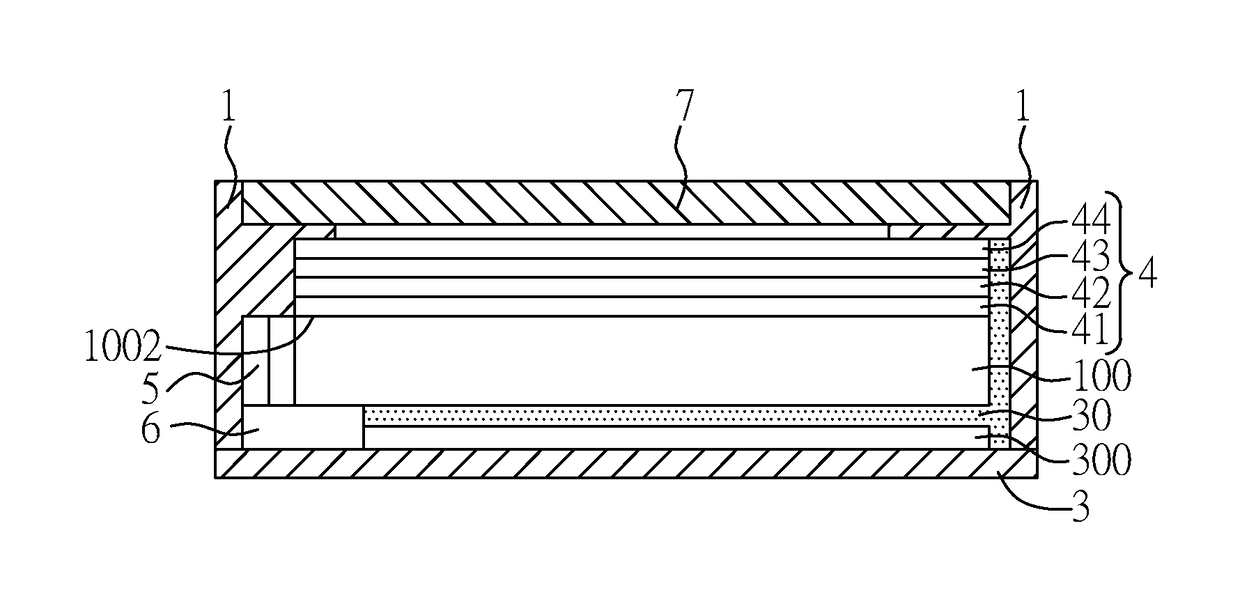
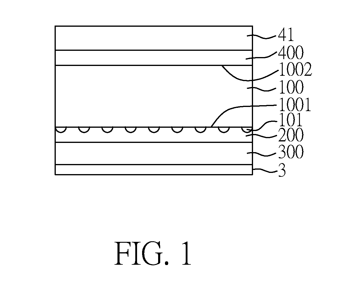
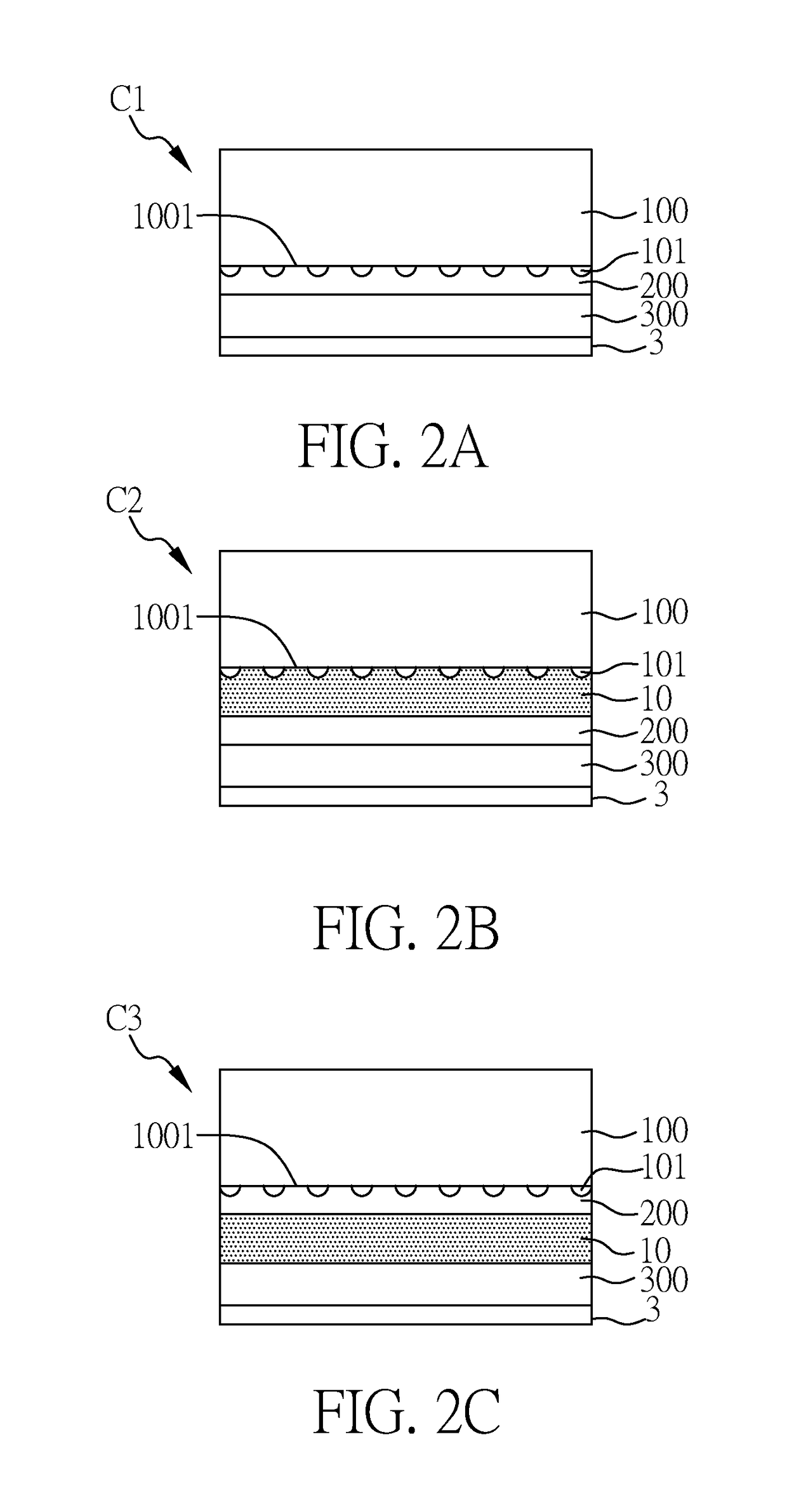
[0015]In one embodiment of the present disclosure, the light guide plate of display device is disposed on or adhered to the reflective layer and / or the light guide plate is disposed on or adhered to the set of optical films, so as to prevent warping and waving during assembling processes of the films, and in turn reduce the risk of ambient water invasion or foreign material defects. Additionally, by using the adhered combination of the decorative film and the reflective layer instead of a backplane, or forming the films through coating, the resulting display device can be further thinned. Other objects, advantages, and novel features of the disclosure will become more apparent from the following detailed description when taken in conjunction with the accompanying drawings.

Problems solved by technology

Consequently, the assembled products tend to have warping, waving, or foreign material defects, and lead to backlight nonuniformity, or inferior display quality.
Moreover, the backplane of the backlight module is typically made of metal materials, and the backplane of the backlight module is heavy, thick, or costly, which is difficult for reducing weight, or manufacturing costs.

Method used


Image

  • Display device and method for manufacturing the same
  • Display device and method for manufacturing the same
  • Display device and method for manufacturing the same

Examples


Embodiment Construction

[0030]Hereinafter, the present disclosure will be described with reference to some embodiments and it is understood that the embodiments are not intended to limit the scope of the present disclosure. Moreover, as the contents disclosed herein should be readily understood and can be implemented by a person skilled in the art, all equivalent changes or modifications which do not depart from the concept of the present disclosure should be encompassed by the appended claims.

[0031]In the following description, the terms like “first” and “second” are used for conveniently explanation of arrangement of, configuration of or relative relations among components, without intention to limit these components in terms of number, order, application, or implementation.

[0032]In addition, in the following embodiments of the present disclosure, the size, the thickness and the ratio of each components in the figure are intended to make a person skilled in the art understand the advantages and the effec...


PUM

PropertyMeasurementUnit
refractive indexaaaaaaaaaa
thicknessaaaaaaaaaa
thicknessaaaaaaaaaa

Abstract

A display device and a method for manufacturing the same are disclosed. The display device includes a backlight module, a display panel, and a decorative film. The backlight module includes: a reflective layer disposed on the decorative film; a light guide plate disposed on the reflective layer, a set of optical films including a first diffusion layer, and at least one refractive layer. The light guide plate has a first surface facing the reflective layer and a second surface opposite to the first surface, and the first diffusion layer is disposed on the second surface. At least one refractive layer is disposed on at least one of the first surface and the second surface, wherein a refractive index of the refractive layer is between 1.15 and 1.45. The display panel is disposed on one side of the set of optical films far away from the light guide plate.

Description

CROSS REFERENCE TO RELATED APPLICATION[0001]This application also claims the benefits of the Chinese Patent Application Serial Numbers 201610411432.0 and 201710404081.5, respectively filed on Jun. 13, 2016 and Jun. 1, 2017, the subject matter of which is incorporated herein by reference.BACKGROUND1. Field[0002]The present disclosure relates to a display device and a method for manufacturing the same, and more particularly to a method for manufacturing a display device by adhering its light guide plate to a reflective layer or a set of optical films.2. Description of Related Art[0003]Liquid crystal display devices (LCD devices) are popular flat panel displays. The liquid crystal display devices have many advantages such as high luminance, light weight, or low power consumption, or have been extensively used as displays of various household appliances, mobile phones, or laptop computers. With the increasing applications of the liquid crystal display devices, consumers require higher d...

Claims


Application Information

Patent Timeline
Patent Type & Authority Applications(United States)
IPC IPC(8): G02F1/1335G02F1/13F21V8/00
CPCG02F1/1336G02F1/13G02F1/133553G02B6/0031G02F1/13362G02B6/0025G02B6/00G02B6/005G02B6/0055G02B6/0065G02F1/133308G02F1/133314
Inventor WANG, HUI-CHICHEN, YEN-LIANGLIN, FANG-HOTING, CHIN-LUNG
Owner INNOLUX CORP
Why Eureka
Try Eureka