

Intravaginal Fertility Device
a fertility device and intravaginal technology, applied in the field of intravaginal fertility devices, can solve the problems of high cost, unfavorable surgical treatment, and health risks of fertility medications, and achieve the effects of reducing the risk of complications
- Summary
- Abstract
- Description
- Claims
- Application Information
AI Technical Summary
Benefits of technology
Problems solved by technology
Method used
Image

Examples
first embodiment
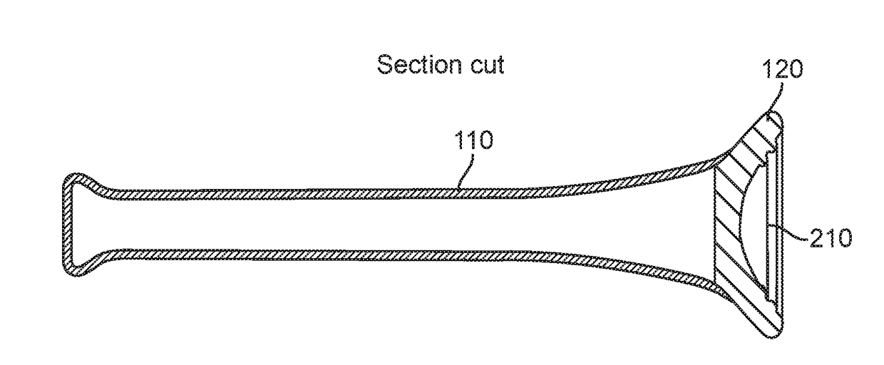
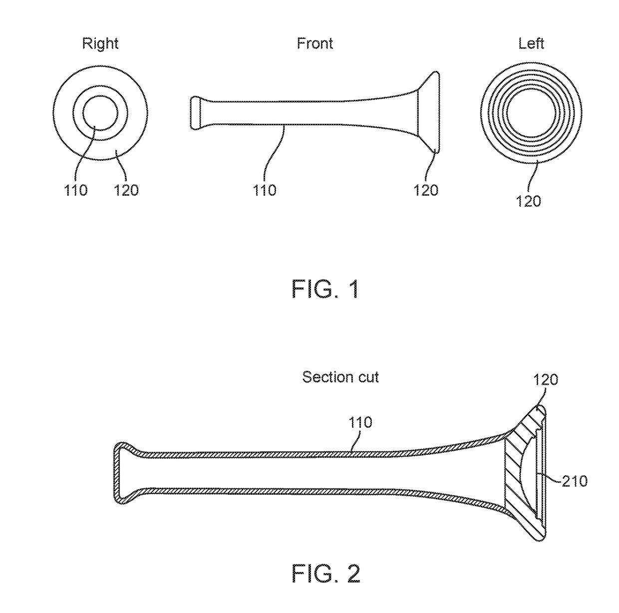
[0018]FIG. 1 illustrates one embodiment of the invention in three views. As shown in FIG. 1, the device has a rigid shaft 110 terminating with a larger diameter concave end cup 120. The end cup is an elastically deformable material such that it can form to the shape of the walls of the vaginal canal. FIG. 2 show additional details of the device according to the invention. As shown in FIG. 2, the end cap has a concave section 210 at the end to facilitate the collection of ejaculate.
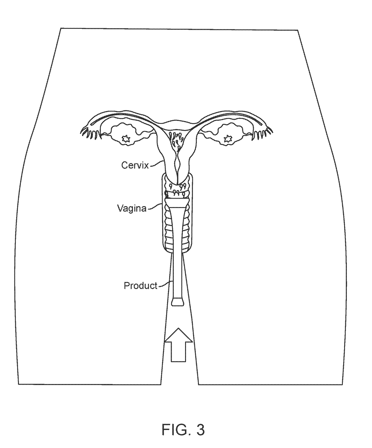
[0019]FIG. 3 illustrates the use of the embodiment of the invention shown in FIGS. 1 and 2. After intercourse resulting in ejaculation, the cup end of the device is inserted into the vaginal opening and slid into a positions at the os of the cervix. As the device travels through the vaginal canal, the sides of the end cup 120 collect ejaculate present in the vaginal canal and present it to the cervix. The end cup 120 remains in the vicinity of the cervix for a prescribed amount of time, for example between...
second embodiment
[0020]FIGS. 4 and 5 illustrate the invention, similar to the embodiment discussed in connection with FIG. 1. The key difference between the two embodiment is that the embodiment shown in FIGS. 4 and 5 is manufactured and assembled differently. As shown in FIG. 5, the device is comprised of a rigid shaft piece 510 and is covered with an elastically deformable material 520. The concave end cap 530 is formed using the deformable materials 520. Use of the device illustrated in FIGS. 4 and 5 is the same as described above for the embodiment shown in FIGS. 1 and 2.
[0021]FIGS. 6 and 7 illustrate a third embodiment of the present invention. FIG. 6 shows the device of the third embodiment prior to use. The device of FIG. 6 includes a shaft 610 and end cap 620, as well as a shell 630. The shaft 610 and shell 630 are made of rigid material; the end cap 620 is made of elastically deformable materials. The shaft protrudes through a hole in the shell 630 and connects to the end cap 620. When asse...
fourth embodiment
[0023]FIG. 10 illustrates a device according to the present invention. The device of FIG. 10 has similar features to the other embodiments already discussed. The device has a shaft assembly 1010, a cap 1020, a shell 1030, and a wirelocker 1040. In this embodiment, the cup 1020 is designed to fold to present a smaller profile to the vaginal opening, and also to detach from the shaft 1010 and shell 1030 assembly. As shown in FIG. 11, the shaft assembly is comprised of two shaft halves, 1010a and 1010b. The cup 1020 is connected to the wirelocker 1040 by a wire-like linkage 1110 such as a length of wire or string. The wirelocker 1040 locks onto a locking feature 1120 on one side of the two-piece shaft 1010a, holding the cup 1020 in position at the end of the shaft assembly 1010 as shown in FIG. 10.
[0024]FIGS. 12 and 13 illustrate the procedure for inserting the device according to the embodiment shown in FIG. 11 into the vaginal canal and placing the cap in proximity to the cervix. The...
PUM
 Abstract
Description
Claims
Application Information