Window Covering and Sensors to Reduce Convection

a technology of convection reduction and window covering, applied in the field of home automation, can solve the problems of air drafts, state of the art has not been solved, uncomfortable to sit in a drafty room, etc., and achieve the effect of reducing air drafts, reducing convection, and reducing drafts

Inactive Publication Date: 2018-01-18
HALL LABS LLC
View PDF2 Cites 8 Cited by
  • Summary
  • Abstract
  • Description
  • Claims
  • Application Information

AI Technical Summary

Benefits of technology

[0004]An automated window covering system is disclosed that overcomes or improves upon the limitations discussed above. In general, the automated window covering system includes a window covering that is adjusted by a microcontroller via a motor. The microcontroller instructs the moter to adjust the window covering based on temperature information received from two temperature sensors. When a temperature gradient is detected that results in convection in front of the window, the window covering is adjusted to reduce convection. Thus, the window covering is capable of resolving the draft-causing temperature gradient while still allowing natural light into the room.
[0005]In one embodiment, a system to reduce drafts in front of a window is described. The system includes a window covering and a motor and gearbox that adjust the window covering. The system also includes a first temperature sensor, a second temperature sensor, and a microcontroller networked to the motor and temperature sensors. The first temperature sensor is positioned above the window covering within a thermal convection zone of a window associated with the window covering, and the second temperature sensor is positioned below the window covering within the thermal convection zone. The microcontroller instructs the motor to adjust the window covering based on a temperature gradient from the first temperature sensor to the second temperature sensor.
[0006]In another embodiment, a method to reduce drafts in front of a window is also described. The method includes measuring a first temperature above a window covering within a thermal convection zone of a window associated with the window covering, measuring a second temperature below the window covering within the thermal convection zone, and calculating a temperature gradient based on the first and second temperatures. The method also includes adjusting the window covering based on the temperature gradient.

Problems solved by technology

Many problems have been addressed by the various systems existing in the prior art, however there are yet still problems that the state of the art have not solved.
It can often be uncomfortable to sit in a drafty room.
One cause of air drafts is uneven heating of air in a room by sunlight through a window.

Method used


Image

  • Window Covering and Sensors to Reduce Convection
  • Window Covering and Sensors to Reduce Convection
  • Window Covering and Sensors to Reduce Convection

Examples


Embodiment Construction

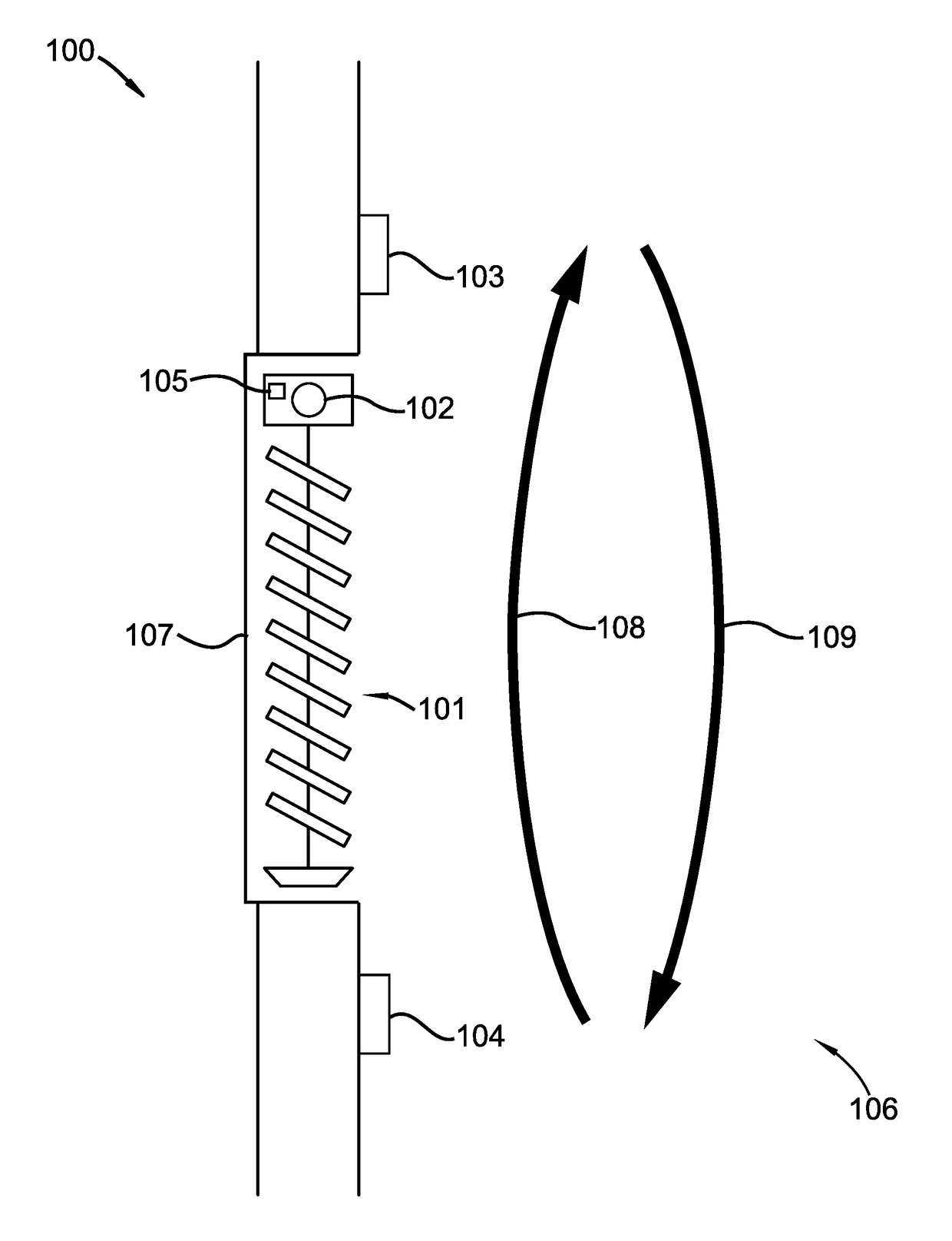
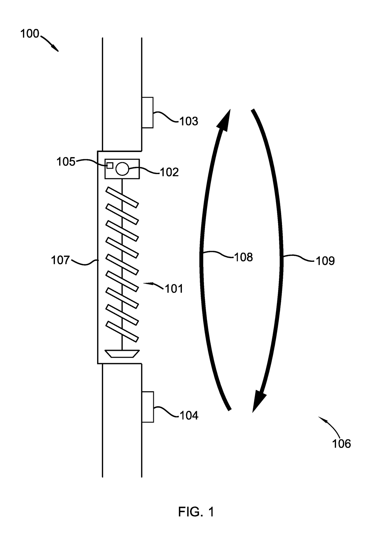
[0020]A detailed description of the claimed invention is provided below by example, with reference to embodiments in the appended figures. Those of skill in the art will recognize that the components and steps of the invention as described by example in the figures below could be arranged and designed in a wide variety of different configurations without departing from the substance of the claimed invention. Thus, the detailed description of the embodiments in the figures is merely representative of embodiments of the invention, and is not intended to limit the scope of the invention as claimed.

[0021]The descriptions of the various embodiments include, in some cases, references to elements described with regard to other embodiments. Such references are provided for convenience to the reader, and are not intended to limit the described elements to only the features described with regard to the other embodiments. Rather, each embodiment is distinct from each other embodiment.

[0022]Thr...


PUM


Abstract

A system to reduce drafts in front of a window is described. The system includes a window covering and a motor and gearbox that adjust the window covering. The system also includes a first temperature sensor, a second temperature sensor, and a microcontroller networked to the motor and temperature sensors. The first temperature sensor is positioned above the window covering within a thermal convection zone of a window associated with the window covering, and the second temperature sensor is positioned below the window covering within the thermal convection zone. The microcontroller instructs the motor to adjust the window covering based on a temperature gradient from the first temperature sensor to the second temperature sensor.

Description

TECHNICAL FIELD[0001]This invention relates generally to the field of home automation, and more specifically to automated window coverings.BACKGROUND[0002]Home automation is a very popular field with a broad consumer market. Automated window covering systems have been developed that operate on a wide variety of inputs to achieve a desired outcome. Some systems seek to maximize the amount of light let in through a window. Others vary the amount of sunlight admitted based on a thermostat. Others seek to provide shade while still allowing natural light to enter. Some systems operate based on geographic locations, others based on photo sensors or time of day. Many problems have been addressed by the various systems existing in the prior art, however there are yet still problems that the state of the art have not solved.[0003]It can often be uncomfortable to sit in a drafty room. One cause of air drafts is uneven heating of air in a room by sunlight through a window. While the current st...

Claims


Application Information

Patent Timeline
Patent Type & Authority Applications(United States)
IPC IPC(8): E06B9/68E06B9/36E06B9/24E06B9/32F24F11/00
CPCE06B9/68E06B9/24E06B9/32E06B2009/6818F24F11/0001E06B2009/6809E06B9/368
Inventor HALL, DAVID R.CARLSON, AUSTINMILES, JEROMEREES, KEVINBRIMHALL, EMILYFOX, JOEKNIGHT, JEDEDIAH
Owner HALL LABS LLC
Why Eureka
Try Eureka