Method and apparatus to facilitate reducing losses in turbine engines

a turbine engine and loss reduction technology, applied in the field of turbine engines, can solve the problems of engine stall, engine efficiency and/or operability margin, engine efficiency reduction, etc., and achieve the effect of facilitating reducing convection and aerodynamic bleed losses

Active Publication Date: 2010-04-27
GENERAL ELECTRIC CO
View PDF9 Cites 10 Cited by
  • Summary
  • Abstract
  • Description
  • Claims
  • Application Information

AI Technical Summary

Benefits of technology

[0005]In one aspect a method for assembling a compressor for use with a turbine is provided. The method includes coupling at least a first stator ring to a second stator ring via at least one fastener sized to extend through at least one stator ring opening. The method further includes coupling a shield assembly to at least one of the first stator ring and the second stator ring to facilitate reducing convection and aerodynamic bleed losses of the at least one stator ring. The shield assembly includes a downstream surface, a retaining portion, and a contoured upstream surface extending from the downstream surface to the retaining portion.
[0006]In another aspect, a turbine assembly is provided. The turbine assembly includes a compressor assembly including at least one flange coupled to at least one stator ring via at least one fastener sized to extend through at least one stator ring opening. The turbine assembly further includes a shield assembly coupled to the at least one stator ring to facilitate reducing convection and aerodynamic bleed losses of the at least one stator ring. The shield assembly includes a downstream surface, a retaining portion, and a contoured upstream surface extending from the downstream surface to the retaining portion.
[0007]In a further aspect, a compressor assembly for use with a turbine is provided. The compressor assembly includes at least one flange coupled to at least one stator ring via at least one fastener sized to extend through at least one stator ring opening. The compressor assembly further includes a shield assembly coupled to the at least one stator ring to facilitate reducing convection and aerodynamic bleed losses of said at least one stator ring. The shield assembly comprises a downstream surface, a retaining portion, and a contoured upstream surface extending from the downstream surface to the retaining portion.

Problems solved by technology

Specifically, the magnitude of steady state clearances and transient radial clearances between the components may affect the turbine efficiency and / or operability margin.
For example, a large transient clearance, or a clearance with significant variation around the circumference of the rotating component may adversely decrease the turbine efficiency and may result in engine stalls.
However, because such U-shaped shields are positioned adjacent the flowpath, the shields may adversely impact engine efficiency, specifically, such shields may increase aerodynamic losses associated with the compressor bleed flow.
In some known compressors, aerodynamic losses are incurred because of windage, convection, and / or pressure losses due to the discharge of the air flow in a large cavity and the turbulence of the flow associated therewith.

Method used


Image

  • Method and apparatus to facilitate reducing losses in turbine engines
  • Method and apparatus to facilitate reducing losses in turbine engines
  • Method and apparatus to facilitate reducing losses in turbine engines

Examples


Embodiment Construction

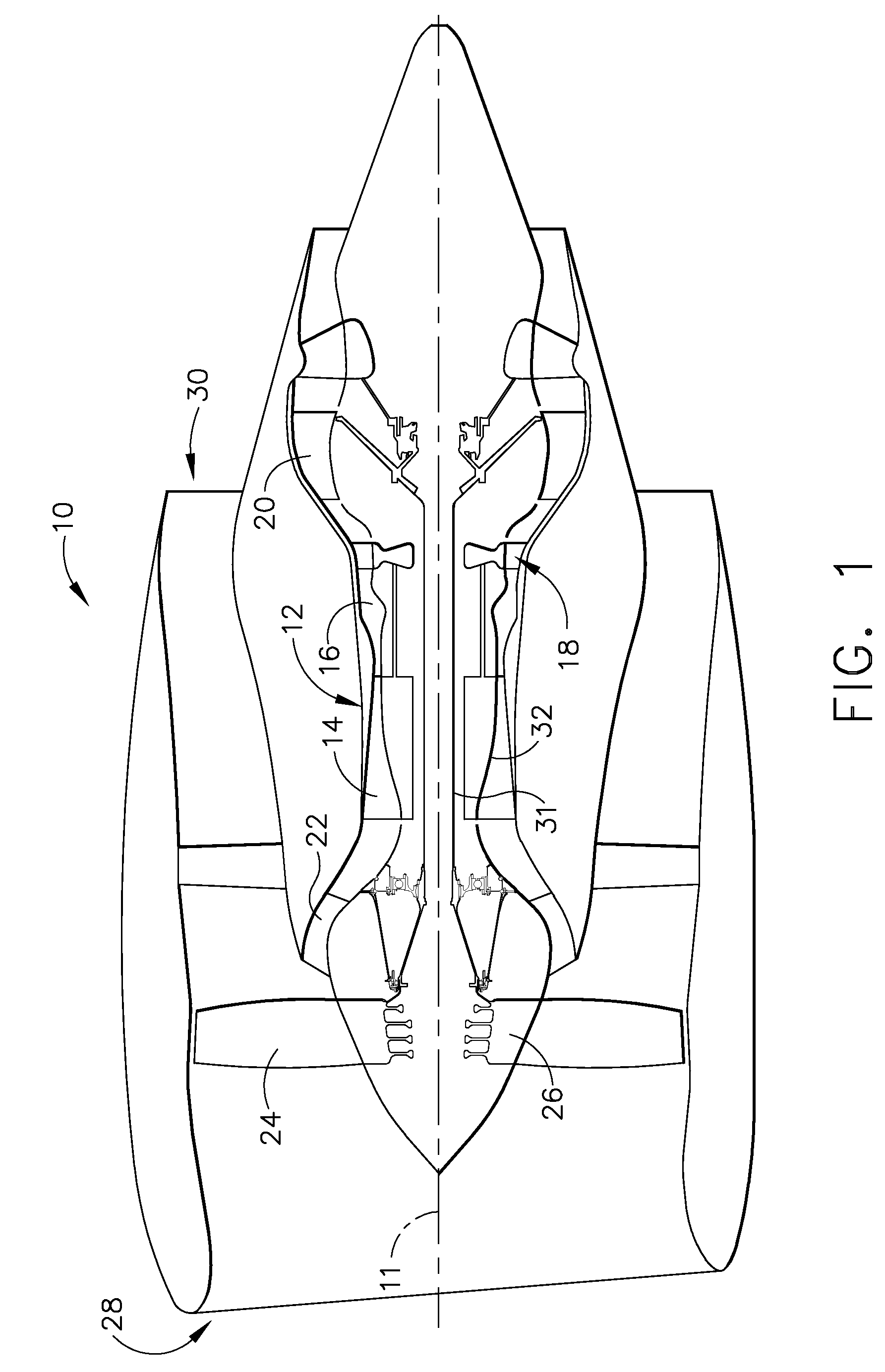
[0014]FIG. 1 is a cross-sectional view of an exemplary turbofan engine assembly 10 having a longitudinal axis 11. In the exemplary embodiment, turbofan engine assembly 10 includes a core gas turbine engine 12 that includes a high-pressure compressor 14, a combustor 16, and a high-pressure turbine 18. Turbofan engine assembly 10 also includes a low-pressure turbine 20 that is coupled axially downstream from core gas turbine engine 12, and a fan assembly 22 that is coupled axially upstream from core gas turbine engine 12. Fan assembly 22 includes an array of fan blades 24 that extend radially outward from a rotor disk 26. Engine 10 has an intake side 28 and an exhaust side 30. In the exemplary embodiment, turbofan engine assembly 10 is a GE90 gas turbine engine that is available from General Electric Company, Cincinnati, Ohio. Core gas turbine engine 12, fan assembly 22, and low-pressure turbine 20 are coupled together by a first rotor shaft 31, and compressor 14 and high-pressure tur...


PUM


Abstract

A method for assembling a compressor for use with a turbine is provided. The method includes coupling at least a first stator ring to a second stator ring via at least one fastener sized to extend through at least one stator ring opening. The method further includes coupling a shield assembly to at least one of the first stator ring and the second stator ring to facilitate reducing convection and aerodynamic bleed losses of the at least one stator ring. The shield assembly includes a downstream surface, a retaining portion, and a contoured upstream surface extending from the downstream surface to the retaining portion.

Description

BACKGROUND OF THE INVENTION[0001]This invention relates generally to turbine engines, and more particularly to methods and apparatus for reducing convection and aerodynamic bleed losses in turbine engines.[0002]The efficiency of at least some known turbines is at least partially affected by the clearances defined between the rotating components and stationary components. Specifically, the magnitude of steady state clearances and transient radial clearances between the components may affect the turbine efficiency and / or operability margin. For example, a large transient clearance, or a clearance with significant variation around the circumference of the rotating component may adversely decrease the turbine efficiency and may result in engine stalls.[0003]As described above, clearances may be affected by the rotor and the stator's transient thermal responses. Generally, known stators are built to be as lightweight as possible to meet engine weight metrics. This low stator weight makes...

Claims


Application Information

Patent Timeline
Patent Type & Authority Patents(United States)
IPC IPC(8): F01D25/28
CPCF01D25/14F01D25/246Y10T29/49245F05D2240/12
Inventor RING, MATTHEW JOSEPHRULLI, SAMUELKIRK, CORYLIU, HSIN-TUANKARAFILLIS, APOSTOLOS
Owner GENERAL ELECTRIC CO
Why Eureka
Try Eureka