Pumped fluid cooling system and method

a pumped fluid and cooling system technology, applied in the field of cooling systems, can solve the problems of low heat capacity and high viscosity, inefficient pumped fluid system, and large values of rsub>convection/sub>, and achieve the effect of efficient cooling a device, decreasing a spread resistance and reducing a convection resistan

Inactive Publication Date: 2006-03-02
COOLIGY INC
View PDF99 Cites 10 Cited by
  • Summary
  • Abstract
  • Description
  • Claims
  • Application Information

AI Technical Summary

Benefits of technology

[0012] In another aspect of the present invention, a method of efficiently cooling a device in a pumped fluid cooling system comprises decreasing a spread resistance between an interface layer of a heat exchanger and the device, decreasing a convection resistance between a fluid and the interface layer of the heat exchanger, wherein the fluid is pumped through the interface layer, and further wherein the fluid has an inlet temperature and an outlet temperature, increasing an advection resistance and adjusting the composition of the fluid to increase the heat capacity per unit mass and decrease the viscosity, wherein the difference between the fluid outlet temperature and the fluid inlet temperature is at least 30% of the difference between a hottest temperature of the fluid in the heat exchanger and the fluid inlet temperature.

Problems solved by technology

These dimensions result in relatively large values of Rconvection.
These relatively large values of Rspread and Rconvection result in an inefficient pumped fluid system.
The characteristics of such fluids include a low heat capacity and a high viscosity and do not function well in a system having a reduced flowrate.

Method used


Image

  • Pumped fluid cooling system and method
  • Pumped fluid cooling system and method
  • Pumped fluid cooling system and method

Examples


Embodiment Construction

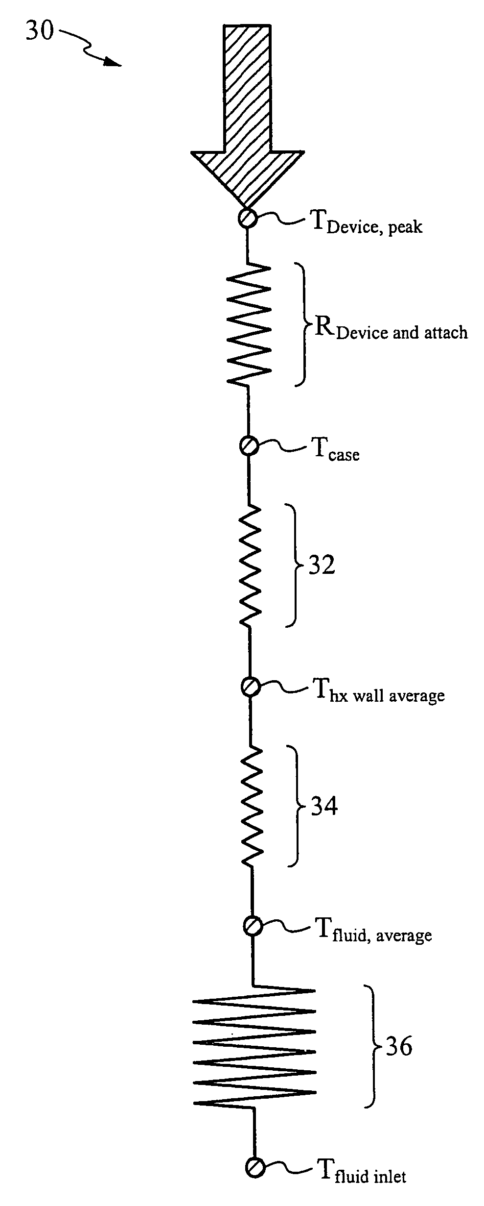
[0028]FIG. 3 is a graphical representation of the preferred embodiment of the present invention. The preferred embodiment of the present invention includes new relative magnitudes of the advection 36, convection 34, and spreading 32 components of the resistance for a pumped fluidic system (PFS) 30, which enable lower pump flowrates and, consequently, pumps that are smaller and consume less power. The new relative magnitudes of these resistances are enabled by a micro hx as described below with feature sizes in the range of 15-300 microns. Still referring to FIG. 3, this micro hx of the PFS 30 of the preferred embodiment of the present invention allows for a smaller spread resistance 32 and smaller convection resistance 34, thereby conserving the temperature budget. This conservation allows for a higher advection 36 component.

[0029] Referring back to the advection formula once again, C / mc where m is the flowrate, reducing the flowrate m will cause the advection 36 component to incre...


PUM


Abstract

The present invention is a pumped fluid cooling system and method. The pumped fluid cooling system and method includes new relative magnitudes of advection, convection and spreading components of the resistance for a pumped fluid system. The pumped fluid cooling system and method also includes adjusting the chemical composition of the working fluid, specifically adjusting the composition and viscosity as the sensitivity to the fluid heat capacity per unit mas increases.

Description

FIELD OF THE INVENTION [0001] The present invention relates generally to the field of cooling systems. More specifically, the present invention relates to the field of pumped fluid cooling systems. BACKGROUND OF THE INVENTION [0002] In current pumped fluid cooling systems as depicted in FIG. 1, the total “temperature budget,” or the difference between the peak device temperature (TDevice, peak) and the temperature of the cold fluid inlet (Tfluid inlet) is consumed by the total heat power (q(W)) flowing through four separate resistances. [0003]FIG. 1 illustrates such a resistance model for an exemplary pumped fluid cooling system. The device / attach resistances (RDevice and attach) dissipate a significant amount of q(W). However, the device / attach resistances are not related to the present invention and need no further explanation. The spreading resistance (Rspread) accounts for spreading the heat from a small device into a larger heat exchanger (hx). The Rspread increases with the ra...

Claims


Application Information

Patent Timeline
Patent Type & Authority Applications(United States)
IPC IPC(8): F28F7/00
CPCF28F3/12F28F2260/02F28F9/0263
Inventor WERNER, DOUGLASGOODSON, KENNETHMUNCH, MARKUPADHYA, GIRISH
Owner COOLIGY INC
Why Eureka
Try Eureka