Sealing High Pressure Flow Devices

a high-pressure flow and fluid flow technology, applied in the direction of liquid fuel engines, machines/engines, mechanical equipment, etc., can solve the problems of cumbersome and disruptive repair, leakage in a short amount of time, cumbersome and laborious repair

Active Publication Date: 2018-01-18
KERR MACHINE CO
View PDF0 Cites 38 Cited by
  • Summary
  • Abstract
  • Description
  • Claims
  • Application Information

AI Technical Summary

Problems solved by technology

Operating a valve in the harsh oilfield conditions can cause erosion of the valve body bore where the seal in the insert abrades against the bore, often resulting in leakage in a short amount of time.
Repairing the valve body, such as by a weld build-up and machining operation, is a cumbersome and disruptive repair in the oilfield.
However, an enumeration of all the different types of val...

Method used


Image

  • Sealing High Pressure Flow Devices
  • Sealing High Pressure Flow Devices
  • Sealing High Pressure Flow Devices

Examples


Embodiment Construction

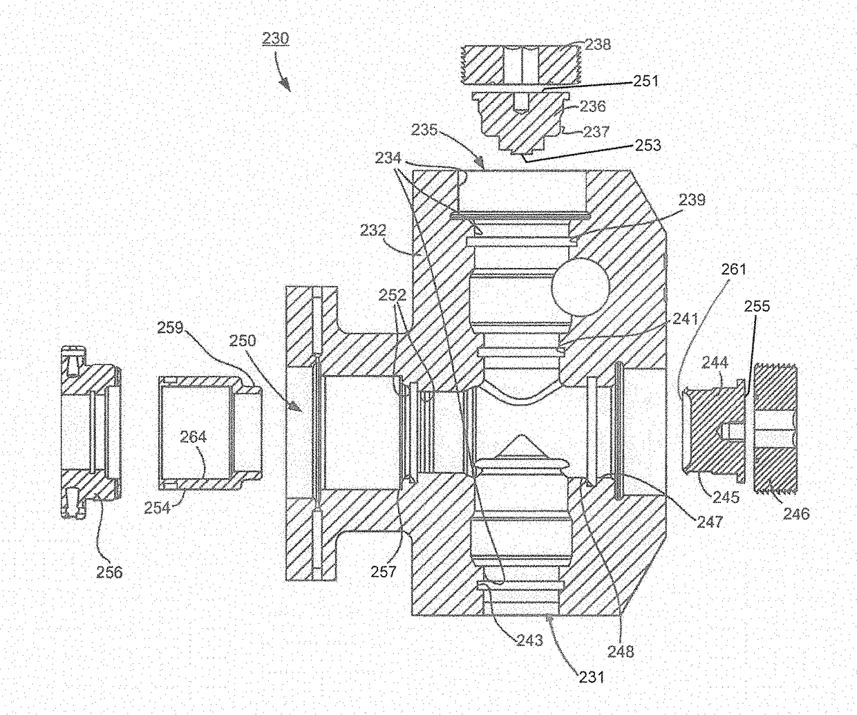
[0026]Initially, this disclosure is by way of example only, not by limitation. The illustrative constructions and associated methods disclosed herein are not limited to use or application for sealing any specific assembly or in any specific environment. That is, the disclosed technology is not limited to use in sealing valves and fluid ends as described in the illustrative embodiments. Thus, although the instrumentalities lo described herein are for the convenience of explanation, shown and described with respect to exemplary embodiments, the skilled artisan understands that the principles herein may be applied equally in sealing other types of high pressure flow devices.

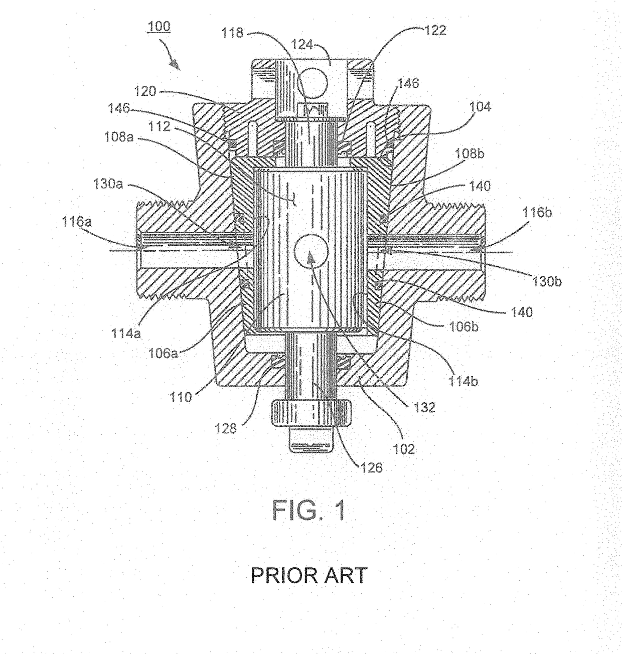
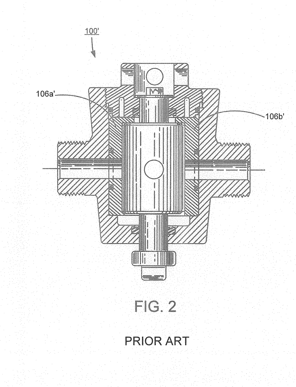
[0027]FIG. 1 is a cross-sectional depiction of a plug valve 100 that is constructed according to previously attempted solutions. The plug valve 100 has a forged valve body 102 forming a tapered internal bore 104. Inserts 106a, 106b in these illustrative embodiments are segments of an open hollow cone. Although two i...


PUM


Abstract

Apparatus and method contemplating a high pressure fluid end assembly having a body defining a body bore and defining a recess in the body intersecting the body bore. A closure is joined to the body and forms a sealing surface. A seal is mounted to the body in the recess and configured to extend from the recess beyond the body bore to seal against the sealing surface formed by the closure.

Description

BACKGROUND[0001]This technology relates generally to sealing fluid flow passages inside flow control devices, such as those particularly suited for use in high pressure oil and gas production and processing systems.[0002]One such type of flow control device is a valve. Generally, a valve forms a flow passage and has a selectively operable closure to open or close the flow passage in order to control a flow of fluid through the valve. The sealing integrity of high pressure valves must withstand not only high operating fluid pressures, presently 15,000 pounds per square inch and higher, but also must do so while controlling the flow of corrosive and / or abrasive fluids that are notorious for eroding the valve internal components in the oil and gas industry. Preferably, the valves can withstand pressures up to at least 22,500 pounds per square inch.[0003]Illustrative embodiments herein are directed to a plug valve although the contemplated embodiments are not so limited. In a plug valve...

Claims


Application Information

Patent Timeline
IPC IPC(8): F16K5/18F16J15/06F15B21/00F16K5/04F15B7/06
CPCF16K5/184F15B7/06F15B21/00F16J15/062F16K5/0492F16K5/0464F16K5/0471F16K5/0485F16K5/0271F16K5/161F16K5/181F04B53/22F04B53/164
Inventor NOWELL, MARK S.FOSTER, KELCY JAKEMAY, MICHAEL EUGENEAYRES, BRANDON SCOTTBARNETT, CHRISTOPHER TODDTHOMAS, MICHAEL COLELAPOINTE, GUY J.
Owner KERR MACHINE CO
Why Eureka
Try Eureka