Material property monitoring using backscatter devices

a technology of backscatter and material properties, applied in the field of monitoring the state of materials of interest, can solve the problems of specialized equipment, large equipment footprint, dangerous or destructive, etc., and achieve the effect of less expensive use and implementation, and convenient and simple use and implementation

Active Publication Date: 2018-01-18
AKSELROD DAVID
View PDF0 Cites 4 Cited by
  • Summary
  • Abstract
  • Description
  • Claims
  • Application Information

AI Technical Summary

Benefits of technology

[0015]It is an objective of the present invention to provide an imaging system and an imaging method that may be comparatively less expensive to use and implement as compared against traditional X-ray, CT-scan, MRI, ultrasound, radar, or the like imaging systems.
[0016]It is another objective of the present invention to provide an imaging system and an imaging method that may be comparatively easy and simple to use and implement as compared against traditional X-ray, CT-scan, MRI, ultrasound, radar, or the like imaging systems.

Problems solved by technology

Prior art imaging techniques, such as, X-ray, CT-scan, MRI, ultrasound, radar, and / or the like generally involve expensive (expensive to buy, lease, use, train, maintain, etc.), specialized, complicated equipment, and / or equipment that may occupy a relatively large footprint.
And in many applications the electromagnetic energy emitted for imaging purposes from some prior art imaging systems may be dangerous or destructive to the object being imaged and thus such imaging must be minimized to prevent problems from overexposure.
A prime example of this is the use of X-rays to image hard (dense) structures in biologic samples, such as teeth and bones in vertebrates; where overexposure to X-rays may lead to undesirable mutations and cancers.
And even in the case of inanimate objects, such objects may also still be prone to deterioration (e.g., becoming brittle) resulting from overexposure to emitted high energy imaging electromagnetic radiation, such as X-rays.
In many instances, if overexposure was not a problem, practitioners would then prefer to utilize such imaging techniques more frequently thus significantly increasing probability of discovering issues earlier in time.
In some instances, such as with cancer patients or with pregnant women, use of X-rays is necessarily restricted.

Method used


Image

  • Material property monitoring using backscatter devices
  • Material property monitoring using backscatter devices
  • Material property monitoring using backscatter devices

Examples


Embodiment Construction

[0175]In the following discussion that addresses a number of embodiments and applications of the present invention, reference is made to the accompanying drawings that form a part thereof, where depictions are made, by way of illustration, of specific embodiments in which the invention may be practiced. It is to be understood that other embodiments may be utilized and changes may be made without departing from the scope of the invention.

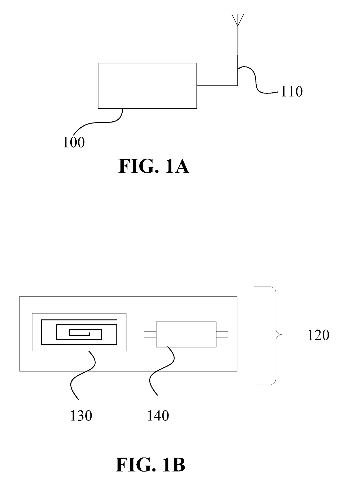
[0176]FIG. 1A may depict a schematic block diagram of a reader 100. In some embodiments, reader 100 may comprise antenna 110. In some embodiments, reader 100 may comprise at least one antenna 110. In some embodiments, reader 100 may comprise one or more antennas 110.

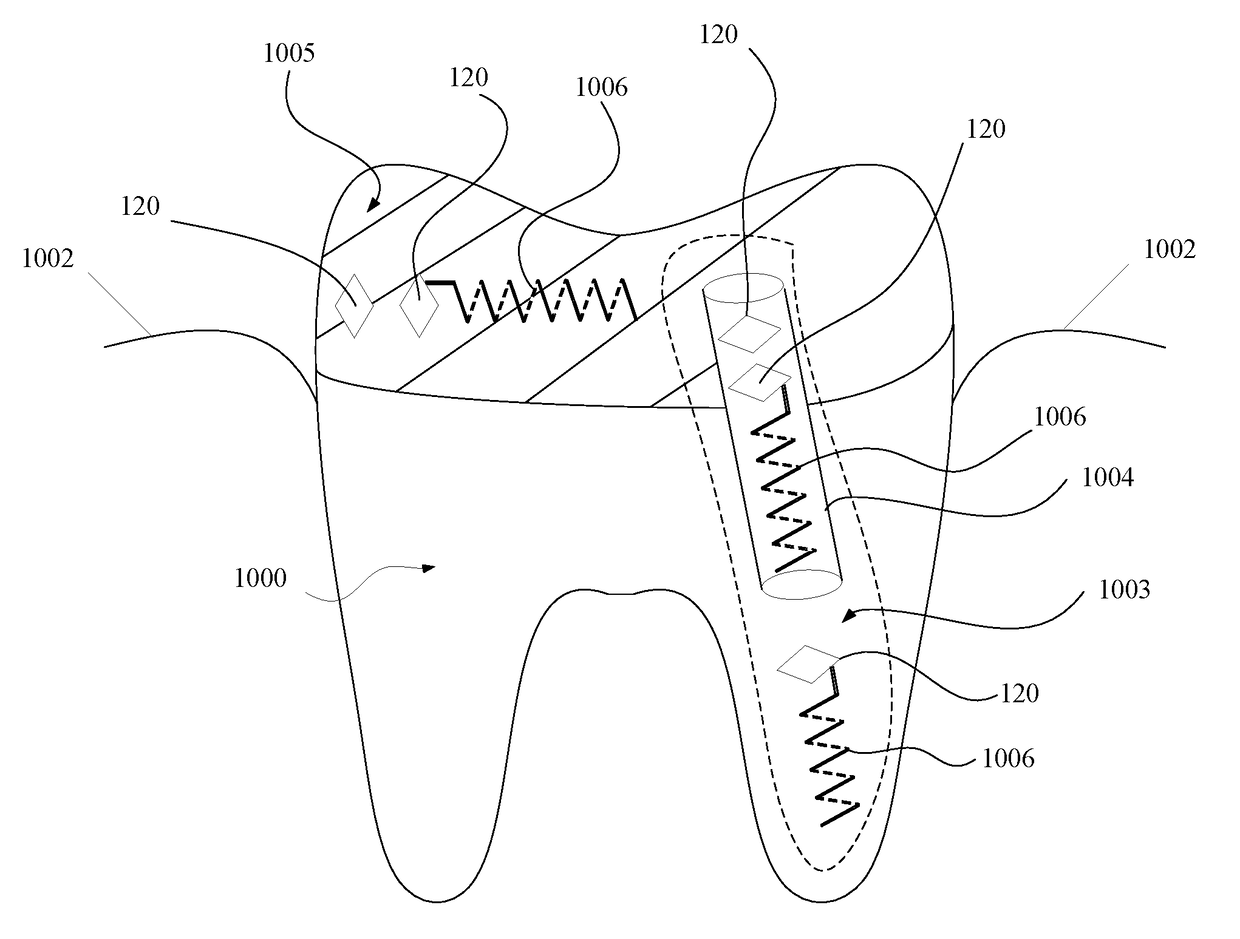
[0177]FIG. 1B may depict a schematic block diagram of a monitoring-sensor-tag 120. In some embodiments, monitoring-sensor-tag 120 may comprise at least one electric circuit 140. In some embodiments, monitoring-sensor-tag 120 may comprise at least one antenna 130 in communication with the ...


PUM

PropertyMeasurementUnit
relative permittivity ∈raaaaaaaaaa
inductanceaaaaaaaaaa
capacitanceaaaaaaaaaa

Abstract

Embodiments of the present invention provide devices (tags), systems, and methods to determine structural integrity and other states of materials-of-interest, such as dental fillings, implants, and root canal posts, to name a few, in a non-invasive and contactless way; and using comparatively safe and/or low energy electromagnetic radiation, such as radio waves. Negligible-sized backscatter-tags with sensors are implanted in such materials-of-interest. Using backscatter imaging technology, the structural integrity and other states of the materials-of-interest may be monitored; which may allow non-invasive and contactless detection of problems such as cracking, bending, excessive pressure, improper temperature, and/or the like. Additionally, initially unknown locations of the implanted negligible-sized backscatter-tags with sensors may be readily determined upon a given scanning (reading) session; and thus mapped to provide an effective image of the material-of-interest.

Description

PRIORITY NOTICE[0001]The present application claims priority under 35 U.S.C. §119(e) to U.S. Provisional Patent Application Ser. No. 62 / 363,481 filed on Jul. 18, 2016; and the present application claims priority under 35 U.S.C. §119(e) to U.S. Provisional Patent Application Ser. No. 62 / 363,551 filed on Jul. 18, 2016, the disclosures of which are both incorporated herein by reference in their entirety.TECHNICAL FIELD OF THE INVENTION[0002]The present invention relates in general to monitoring states of materials of interest and, more specifically, to monitoring states of materials of interest using backscatter sensor tags and where the materials of interest may have uses in dental, medical, and / or construction fields.COPYRIGHT AND TRADEMARK NOTICE[0003]A portion of the disclosure of this patent application may contain material that is subject to copyright protection. The owner has no objection to the facsimile reproduction by anyone of the patent document or the patent disclosure, as...

Claims


Application Information

Patent Timeline
Patent Type & Authority Applications(United States)
IPC IPC(8): G01N27/02A61C13/30A61B5/053
CPCG01N27/02A61B5/053A61B90/39A61C2201/005A61C5/70A61C13/30A61B2562/0214A61C5/50A61C2204/005A61C5/00A61C19/04
Inventor AKSELROD, DAVID
Owner AKSELROD DAVID
Why Eureka
Try Eureka