
Floor Debris Removal Apparatus

a technology for debris removal and floor, applied in the direction of brushes, etc., can solve the problems of irritating smaller particles and lack of integrated channel systems for dispersing liquid, and achieve the effect of moistening the plurality of bristles

Inactive Publication Date: 2018-01-25
ROLAND GYL
View PDF16 Cites 2 Cited by
  • Summary
  • Abstract
  • Description
  • Claims
  • Application Information

AI Technical Summary

Benefits of technology

This invention is a floor debris removal tool that helps minimize the number of dust and particles swept into the air during cleaning. It includes a broom with a reservoir attached to it, which releases liquid into the channel of the broom through a nozzle. The liquid is then moved out of the nozzle through the bristles, moistening them. This tool has several technical benefits, including reducing pulmonary irritation, lessening the burden of external water sources, and allowing user control over moisture dispersion.

Problems solved by technology

Standard sweeping relocates and organizes floor debris but also irritates smaller particulates of dust and debris into the immediate atmosphere, where these smaller particulates of dust and debris may be inhaled by the person using the broom or other people in the vicinity.
These known devices do not provide an integrated channel system to disperse the liquid onto the broom bristles, however, thereby providing all the conveniences of a broom shaft without the imposition of external hoses.

Method used


Image

  • Floor Debris Removal Apparatus
  • Floor Debris Removal Apparatus
  • Floor Debris Removal Apparatus

Examples


Embodiment Construction

[0017]Reference is made herein to the attached drawings. Like reference numerals are used throughout the drawings to depict like or similar elements of the floor debris removal apparatus. The figures are intended for representative purposes only and should not be considered to be limiting in any respect. Unless specifically limited to a single unit, “a” is intended to be equivalent to “one or more” throughout the present disclosure.

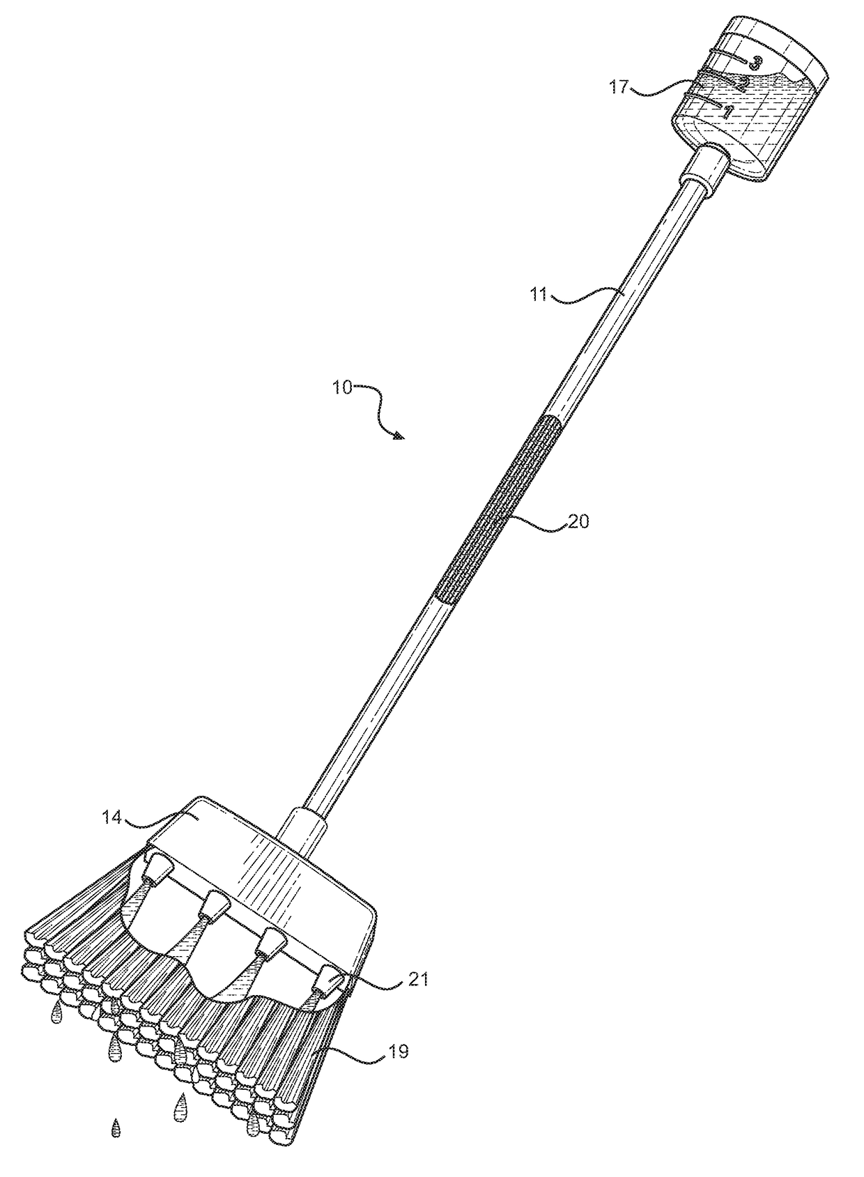
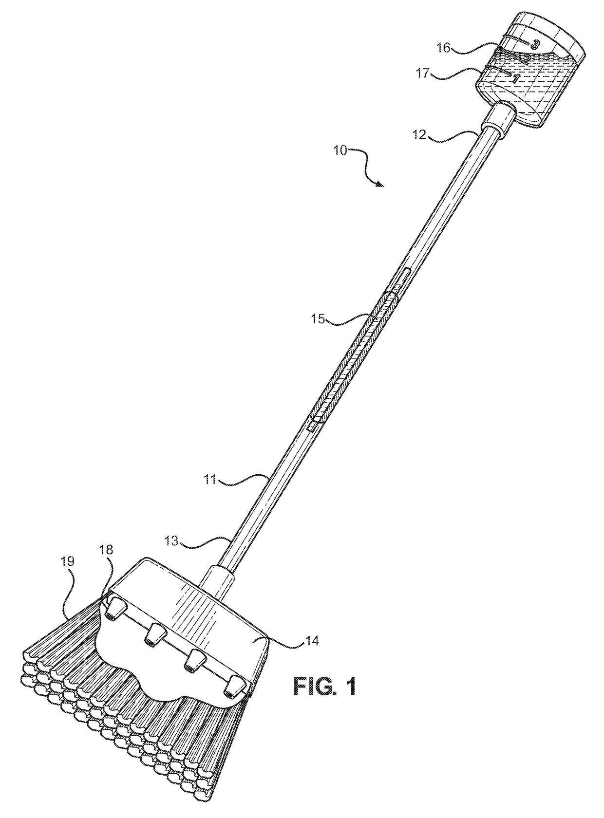
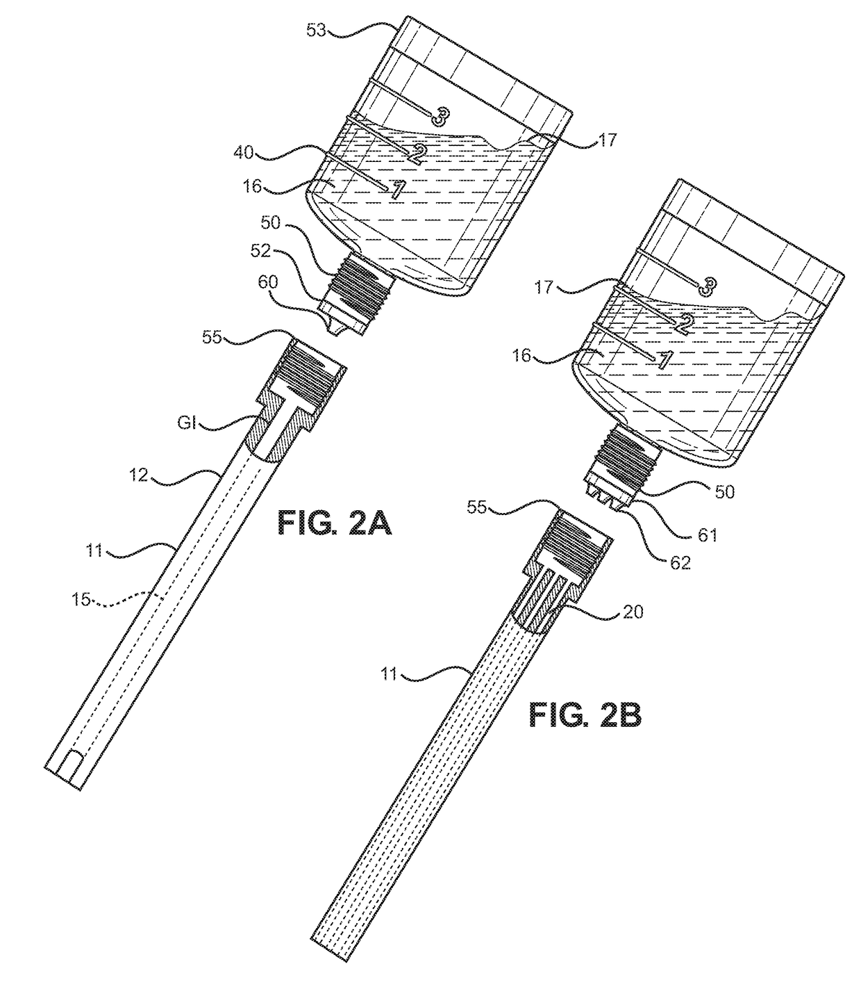
[0018]Referring now to FIG. 1, there is shown a perspective view of an embodiment of the floor debris removal apparatus 10. The floor debris removal apparatus 10 comprises a shaft 11 having a first end 12 opposed to a second end 13. A brush head 14 is affixed to the second end 13 of the shaft 11. A channel 15 is disposed within the interior of the shaft 11 and runs from the first end 12 of the shaft 11 to the second end 13 of the shaft 11. The channel 15 is in fluid communication to nozzles 18 disposed on the brush head 14. A reservoir 16 is removably fas...


PUM


Abstract

A broom for minimizing the aggregation of dust and particulates when sweeping. The broom includes a shaft having a first end and a second end. A broom head having a plurality of bristles is affixed to the second end of the shaft, wherein a channel is disposed within the shaft. The channel is in fluid communication with a nozzle disposed on the broom head, wherein the bristles conceal the nozzle. A reservoir is removably fastened to the first end of the shaft. When fastened to the shaft, the reservoir is in fluid communication with the channel. The reservoir can to excrete a quantity of liquid into the channel and out of the nozzle, thereby moistening the bristle.

Description

CROSS REFERENCE TO RELATED APPLICATIONS[0001]This application claims the benefit of U.S. Provisional Application No. 62 / 364,521 filed on Jul. 20, 2016. The above identified patent application is herein incorporated by reference in its entirety to provide continuity of disclosure.BACKGROUND OF THE INVENTION[0002]The present invention relates to floor debris removal tools. Specifically, the present invention provides a broom having a shaft with an interior channel for dispensing a quantity of a liquid onto a plurality of bristles to reduce the number of atmospheric particulates generated by sweeping with a broom.[0003]When dust, dirt, crumbs and other debris are scattered on a floor, people typically use a broom to sweep it up and throw it away. Standard sweeping relocates and organizes floor debris but also irritates smaller particulates of dust and debris into the immediate atmosphere, where these smaller particulates of dust and debris may be inhaled by the person using the broom o...

Claims


Application Information

Patent Timeline
Patent Type & Authority Applications(United States)
IPC IPC(8): A46B11/00
CPCA46B11/0041A46B11/0062A46B2200/302A46B11/0079A46B11/0096
Inventor ROLAND, GYL
Owner ROLAND GYL
Learn More