
Blue emitters for use in organic electroluminescence devices

a technology of electroluminescence device and blue emitter, which is applied in the direction of luminescent composition, organic chemistry, chemistry apparatus and processes, etc., can solve the problems of high inefficiency of up-shifting of tris(8-hydroxyquinolinate)aluminum emission to the blue region, low performance level of current available device, and many disadvantages, etc., to achieve excellent color purity and excellent thermal stability

Active Publication Date: 2015-07-21
LG DISPLAY CO LTD
View PDF44 Cites 1 Cited by
  • Summary
  • Abstract
  • Description
  • Claims
  • Application Information

AI Technical Summary

Benefits of technology

[0015]The present disclosure relates to a new class of blue emitting materials comprised of 1,1′-binaphthyl derivatives for use in OLED devices which will offer many advantages such as low operation voltages, uniform light emission with spectrum spreading from blue to longer wavelengths, thermal stability, electrochemical stability, and charge transport capability.
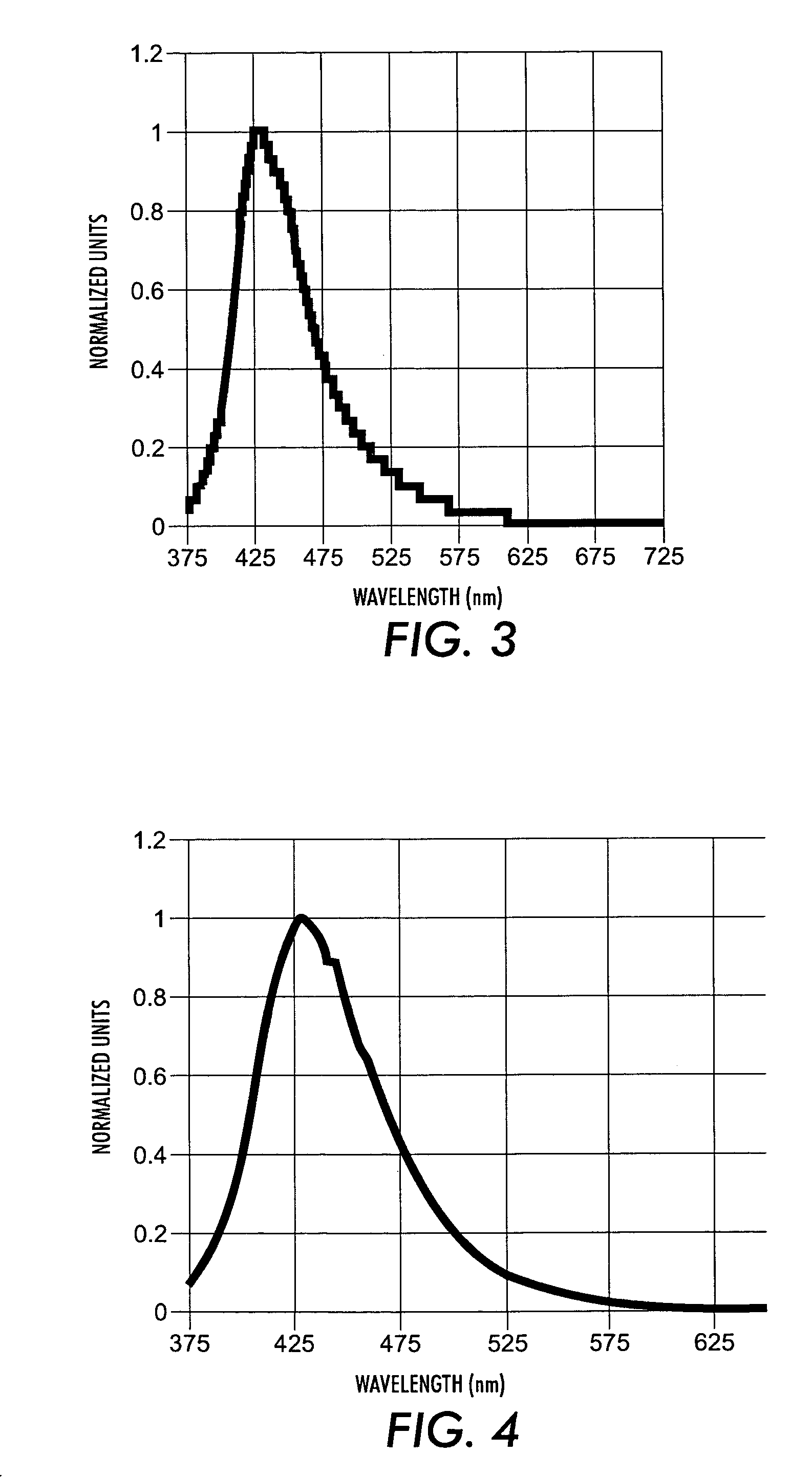
[0021]The luminescent or light emitting 1,1′-binaphthyl derivatives illustrated herein possess in embodiment several advantages. For example, these compounds exhibit strong fluorescence in the solid state in the region of from about 400 nanometers to longer wavelengths of, for example, about 600 nanometers; they have the ability of forming thin films with excellent thermal stability by vacuum evaporation; they are stable; and they can also be blended with a broad scope of fluorescent or phosphorescent materials to form a common phase.
[0022]A preferred structure for a light emitting component comprised of a 1,1′-binaphthyl derivative with excellent color purity could be illustrated by Formula (II). This type of compound will allow color tuning by the addition of further conjugation at the 4 and 4′ positions.
[0024]A preferred structure for a light emitting component comprised of a 1,1′-binaphthyl derivative with good amorphous properties could be illustrated by Formula (III). These types of compounds will form excellent thin films since the addition of groups at the 2 and 2′ positions will minimize crystal packing and molecular aggregation within the device.
[0028]In certain embodiments, this disclosure relates to organic EL devices that are comprised in the following order of a supporting substrate of, for example, glass, an anode, an optional buffer layer, an organic hole transporting layer, an organic light emitting 1,1′-binaphthyl derivatives layer, and an optional electron transporting layer, and in contact therewith a low work function metal as a cathode, wherein the light emitting layer contains at least one luminescent 1,1′-binaphthyl derivative illustrated and encompassed by the formulas recited herein, for example Formula (I); and layered EL devices with a light emitting layer comprised of a luminescent composition comprised of a 1,1′-binaphthyl derivative illustrated by, for example, Formula (I) as a host component capable of sustaining hole-electron recombination and a guest fluorescent or phosphorescent material capable of emitting light in response to energy released by the hole-electron recombination. The light emitting layer may be formed by vacuum deposition from evaporation of the fluorescent 1,1′-binapthyl derivative, and wherein the presence of the fluorescent material, permits a wide latitude of wavelengths of light emission and may enable the enhancement of electroluminescent efficiency and improvements in device operation stability.

Problems solved by technology

However, these devices require excitation voltages on the order of 100 volts or greater.
While recent progress in organic EL research has elevated the potential of organic EL devices for widespread applications, the performance levels of current available devices, especially with respect to blue emission, may still be below expectations.
However, up-shifting of the tris(8-hydroxyquinolinate)aluminum emission to blue region is believed to be highly inefficient.
Although there have been several disclosures describing blue-emitting organic EL devices, for example in U.S. Pat. Nos. 5,151,629 and 5,516,577, their performance characteristics still possess many disadvantages such as poor emission hue, high operation voltages, low luminance, and poor operation stability.

Method used


Image

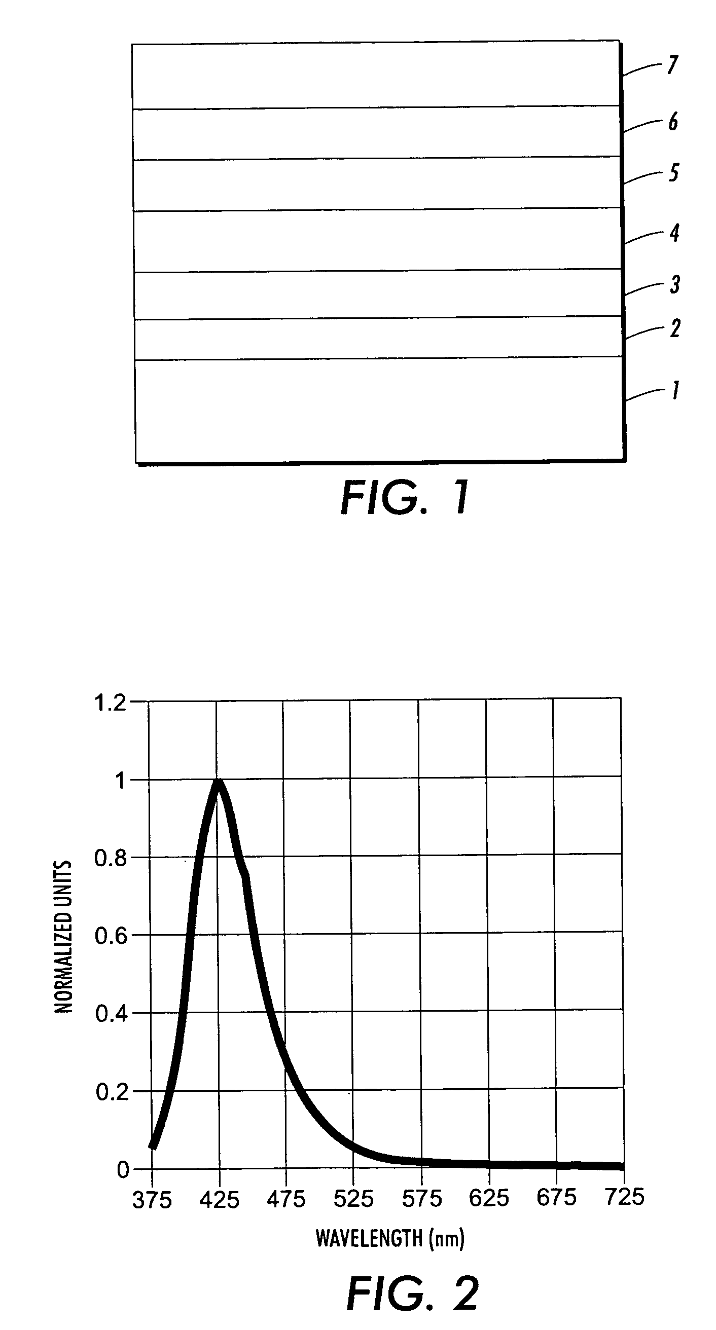
  • Blue emitters for use in organic electroluminescence devices
  • Blue emitters for use in organic electroluminescence devices
  • Blue emitters for use in organic electroluminescence devices

Examples


examples

[0077]More detailed description of examples of the disclosure will be given in the following examples, which are not intended to restrict the scope of the development.

example i

Synthesis of 4,4′-dibromo-1,1′-binaphthyl (Compound 9)

[0078]The compound, 1,1′-binaphthyl (10 g) was placed into a 1 L 3-necked flask equipped with a drying tube and addition funnel. The 1,1′-binaphthyl was dissolved in 600 mL of dichloromethane and was cooled to 0° C. on an ice bath. The bromine (4.25 mL) was placed into the addition funnel and diluted with 50 mL of dichloromethane. The bromine solution was added slowly to the reaction. The reaction was stirred for 3 hours and then a saturated aqueous solution of sodium thiosulfate (200 mL) was added which was stirred vigorously for 1 hour. The organic layer was removed and the aqueous layer was extracted with 2×200 mL of dichloromethane. The organic layers were collected, dried and the solvent removed under reduced pressure to give a brown powder which was treated with a 50 / 50 mixture of filtrol and alumina in toluene. The mixture was filtered and the solvent was removed under reduced pressure to give 15.3 g of a white powder. Thi...

example ii

Synthesis of 4,4′-[(4-t-butyl)diphenyl]-1,1′-binaphthyl (Compound 11)

[0079]The 4,4′-dibromo-1,1′-binaphthyl (5 g) and 4-t-butylphenyl boronic acid (3.3 g) were dissolved in toluene (75 mL) and ethanol (15 mL) under argon. A 2.0M aqueous potassium carbonate solution was added (22 mL) and the solution was purged with argon. The tetrakis(triphenylphosphine)palladium(0) (0.45 g) was added and the mixture was heated at reflux for 48 hours. After cooling, the layers were separated and the organic layer was extracted with 5% HCl and then several times with water. The organic layer was collected, dried and the solvent removed under reduced pressure to give a yellow powder. The solid was purified by sublimation to yield 4.78 g of the desired compound which has a melting point of 270° C. The structure of this compound was confirmed by proton NMR.


PUM

PropertyMeasurementUnit
thicknessaaaaaaaaaa
thicknessaaaaaaaaaa
thicknessaaaaaaaaaa

Abstract

An electroluminescent (EL) is provided comprising an anode, an organic electroluminescent element, and a cathode wherein the electroluminescent element contains, for example, a fluorescent 1,1′-binaphthyl derivative component of Formula (I) wherein R1, R2, R3 and R4 are individual substituents or a group of substituents, each of which may be selected from the group consisting of hydrogen, or alkyl of from 1 to about 25 carbon atoms; an alicyclic alkyl of from 3 to 15 carbon atoms; an aryl or substituted aryl with about 6 to about 30 carbon atoms; carbon atoms from 4 to 24 necessary to complete a fused aromatic ring of naphthalene, anthracene, perylene and the like; an alicyclic alkyl group with from about 3 to about 15 carbon atoms; a silicon atom which can be substituted with a trimethyl, diphenylmethyl, triphenyl group and the like; heteroaryl or substituted heteroaryl of from 5 to 24 carbon atoms, carbon atoms necessary to complete a fused heteroaromatic ring of furyl, thienyl, pyridyl, quinolinyl and other heterocyclic systems; an alkoxy, amino, alkyl amino or aryl amino of from 1 to about 25 carbon atoms; a halogen, a cyano group, and the like.

Description

BACKGROUND[0001]This disclosure relates to organic light emitting devices (OLEDs), and finds particular application in conjunction with display devices utilizing electroluminescence technology.[0002]Disclosed herein are organic electroluminescent (EL) devices and, more specifically, organic EL devices with a number of excellent performance characteristics inclusive of the enablement of blue emitting EL devices. These devices contain luminescent components or a luminescent component with excellent high thermal stability, film forming characteristics and intense blue fluorescence. Organic EL devices are desired that are capable of providing uniform luminescence, saturated color especially in the blue regions of the visible spectrum, and low driving voltages. The organic EL devices disclosed herein enable the above characteristics. These devices contain organic luminescent materials or light emitting components comprised of fluorescent 1,1′-binaphthyl derivatives. These devices can be ...

Claims


Application Information

Patent Timeline
Patent Type & Authority Patents(United States)
IPC IPC(8): H01L51/54C09K11/06H01L51/00H01L51/50C07C15/24C07C25/22C07C43/20C07F7/08
CPCC09K11/06H01L51/0058C09K2211/1007C09K2211/1011C09K2211/1014C09K2211/1044C09K2211/1074C09K2211/1092H01L51/0067H01L51/0081H10K85/626H10K85/654H10K85/324
Inventor COGGAN, JENNIFER A.HU, NAN-XINGAZIZ, HANY
Owner LG DISPLAY CO LTD
Learn More