Microscope

a microscope and optical lens technology, applied in the field of microscopes, can solve the problems of affecting the quality of the image, and taking a long time to perform the positioning operation, so as to achieve the effect of suppressing the cos

Inactive Publication Date: 2018-01-25
SHIMADZU CORP
View PDF2 Cites 7 Cited by
  • Summary
  • Abstract
  • Description
  • Claims
  • Application Information

AI Technical Summary

Benefits of technology

[0026]According to the present invention, it is possible to achieve a microscope in which distortion and blind spots do not occur in an image used for positioning a sample and costs can be suppressed by using a commercially available imaging device.

Problems solved by technology

For this reason, in the positioning operation, in order to search for the position of the measurement object in the sample S, the operation of moving the sample S little by little while monitoring the image needs be performed, and thus, it takes much time to perform the positioning operation.
In addition, since the Cassegrain mirror has a shallow depth of focus (several μm), it is also difficult to align the position of the sample in the vertical direction with the focus, which is also a factor taking much time for the operation.

Method used


Image

  • Microscope
  • Microscope
  • Microscope

Examples


Embodiment Construction

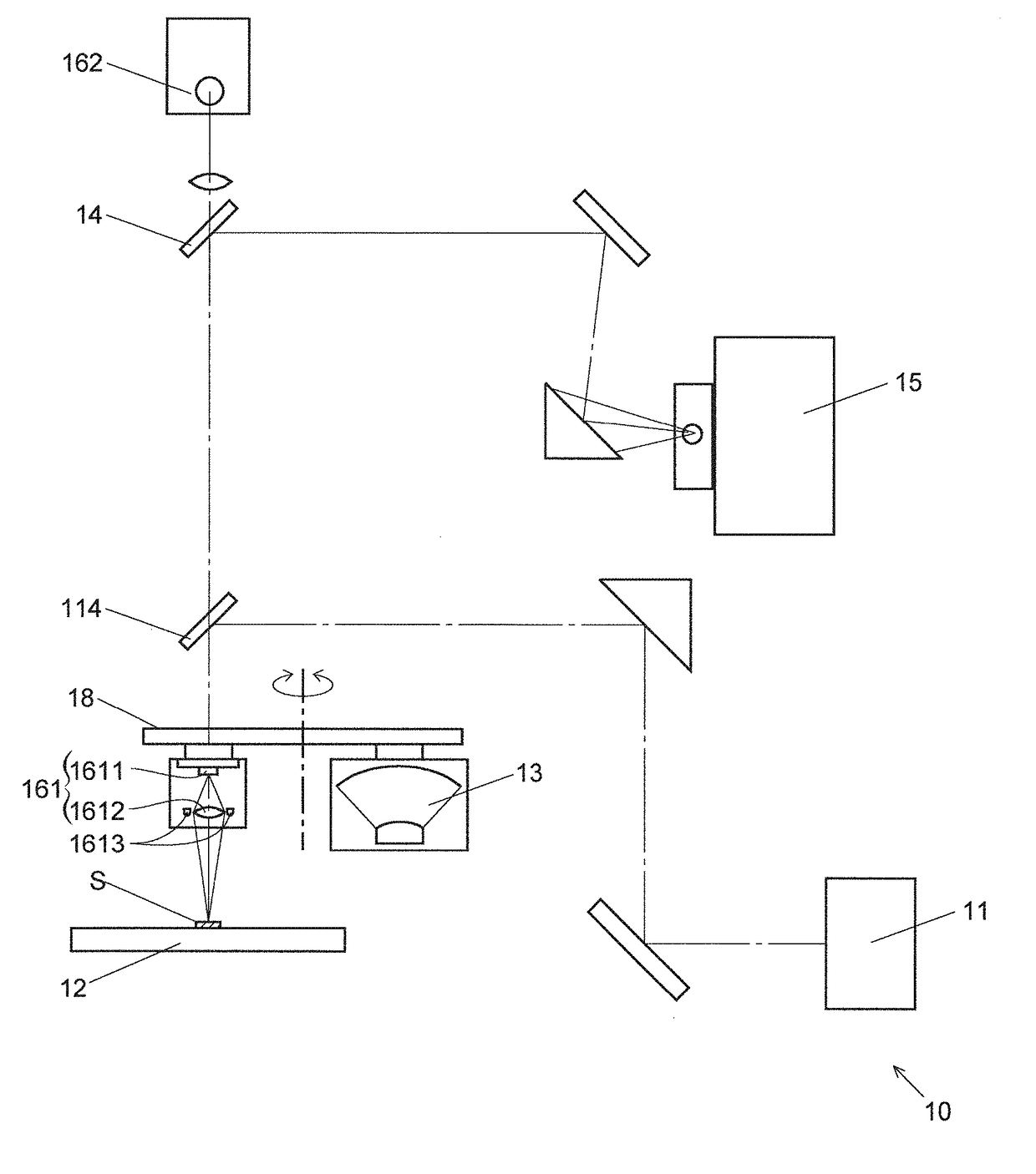
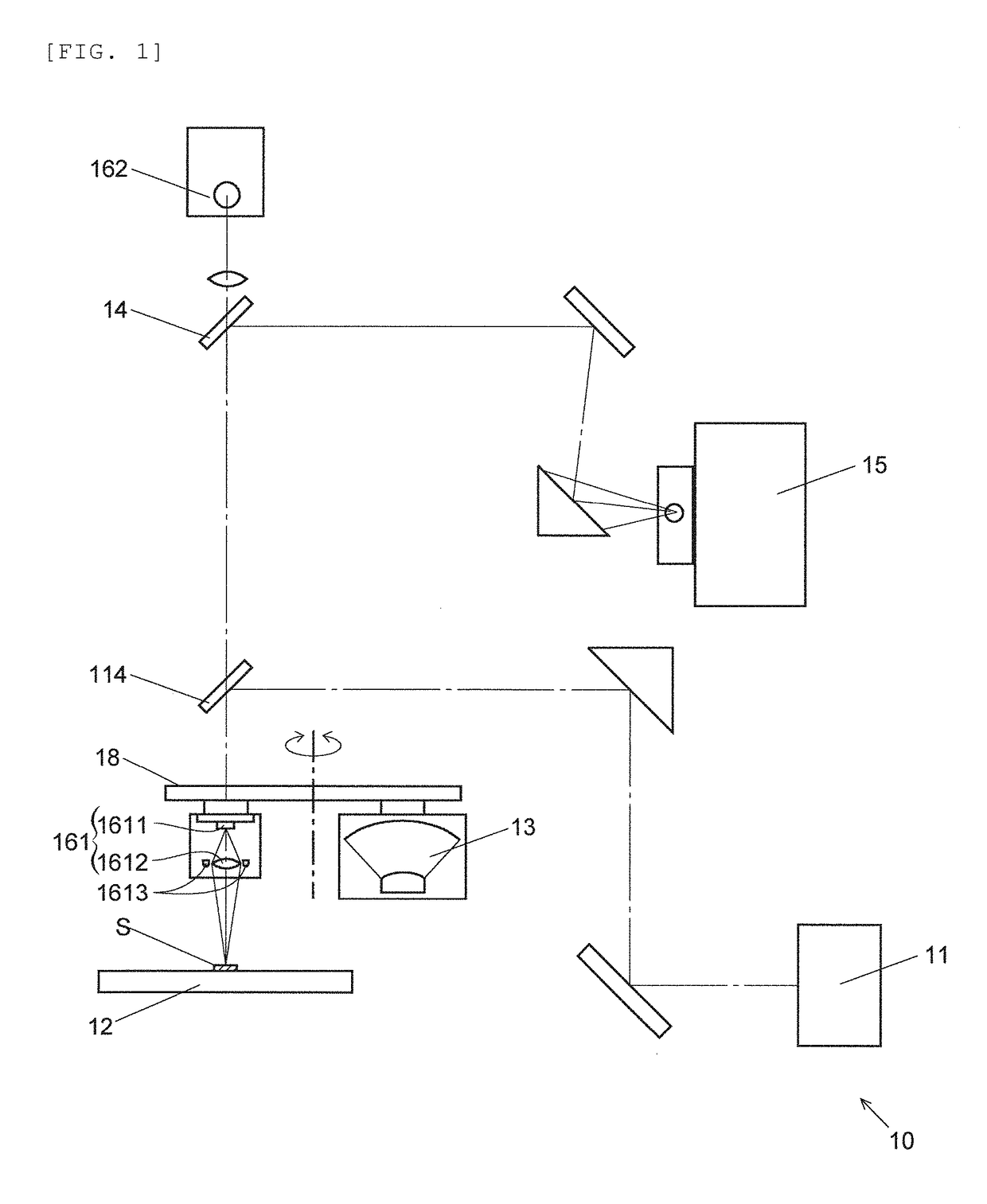
[0033]A microscope according to an embodiment of the present invention will be described with reference to FIGS. 1 to 3.

[0034]FIG. 1 is a schematic configuration diagram illustrating main components of a microscope 10 according to the embodiment. The microscope 10 according to the embodiment is an infrared microscope and is configured to include an infrared light source 11, a sample stage 12, a beam splitter 14, an infrared light detector 15, a revolver 18, and the like. The sample stage 12, the beam splitter 14, and the infrared light detector 15 are the same as those used in the above-described infrared microscope 90 of the related art and the like, and thus, the detailed description thereof will be omitted. In addition, in the infrared microscope 90 and the like, the light source 91 is configured so as to switch between the infrared light source 911 and the visible light source 912, but in the embodiment, only the infrared light source 11 is provided at a position corresponding t...


PUM


Abstract

A microscope equipped with an imaging device used for the positioning of a sample, the microscope capable of removing distortion and blind spots from an image generated by the imaging device and reducing cost by using a commercially available imaging device. A sample holder for holding a sample; a measurement light source for irradiating the sample held by the sample holder with irradiation light; a focusing optical element for focusing measurement light derived from the irradiation light transmitted through or reflected from the sample; a detection unit for detecting the measurement light focused by the focusing optical element; an image capture device for capturing the image of the sample; and an objective optical system switching unit arranged to switch either the focusing optical element or the image capture device with the other to a position facing the sample.

Description

TECHNICAL FIELD[0001]The present invention relates to a microscope such as an infrared microscope or an ultraviolet microscope.BACKGROUND ART[0002]In infrared microscopes and ultraviolet microscopes, in general, before performing actual measurement by using infrared light or ultraviolet light, a positioning operation of capturing an image of a sample with visible light, specifying which position to be measured in the sample on the basis of the obtained image, and correcting the position of the sample so that the position is included in a measurement range is performed.[0003]As an example, a typical infrared microscope 90 of the related art is illustrated in FIG. 4 as a schematic diagram. The infrared microscope 90 is configured to include a light source 91, a sample stage 92, a Cassegrain mirror 93, a beam splitter 94, an infrared light detector 95, and a visible light image capture device 96. The light source 91 is configured to include an infrared light source 911 and a visible li...

Claims


Application Information

Patent Timeline
Patent Type & Authority Applications(United States)
IPC IPC(8): G02B21/36G02B21/24G02B21/06
CPCG02B21/362G02B21/06G02B21/361G02B21/248H04N5/2256G02B17/061G02B21/04G02B21/18G02B21/082H04N23/56
Inventor UEDA, ATSUSHI
Owner SHIMADZU CORP
Why Eureka
Try Eureka