High-voltage power unit and mass spectrometer using the power unit

a power unit and power technology, applied in the field of high-voltage power units and mass spectrometers using power units, can solve the problems of affecting the accuracy of analysis, spiking discharge may occur to break the relay, and it takes a long time to switch the polarity, so as to reduce the mis-detection of ions, both positive and negative, and suppress the cost

Active Publication Date: 2015-10-08
SHIMADZU CORP
View PDF7 Cites 8 Cited by
  • Summary
  • Abstract
  • Description
  • Claims
  • Application Information

AI Technical Summary

Benefits of technology

[0029]In the high-voltage power unit according to the present invention, high-speed switching of an output voltage between positive and negative polarities can be achieved while the cost can be suppressed to the utmost without increase as compared with the conventional unit. Consequently, in a mass spectrometer using the high-voltage power unit according to the present invention for example, a cycle time of alternate switching between positive ion detection and negative ion detection can be decreased, and mis-detection of ions, both positive and negative, can be reduced thereby.

Problems solved by technology

In a high-voltage power unit using a reed relay, when switching the polarity of the output voltage, spike discharges may occur to break the relay.
Consequently, it takes some time to switch the polarity.
This causes a problem of affecting the accuracy of an analysis.
However, this entails such disadvantages as a significant cost hike of the circuits and an increase in necessary electric energy.
However, this entails such disadvantages as an increased power loss in the resistor 51 and a necessity of using expensive resistors which can withstand large electric power.
Therefore, there is a theoretical limit, in the first place, on the attempt of increasing the polarity switching speed by increasing the overshoot.
However, in such a high-voltage power unit, a large number of pulse transformers are needed, and for driving each of these pulse transformers, drive circuits are also needed.
Therefore, it is unavoidable that such a power unit becomes quite expensive.

Method used


Image

  • High-voltage power unit and mass spectrometer using the power unit
  • High-voltage power unit and mass spectrometer using the power unit
  • High-voltage power unit and mass spectrometer using the power unit

Examples


Embodiment Construction

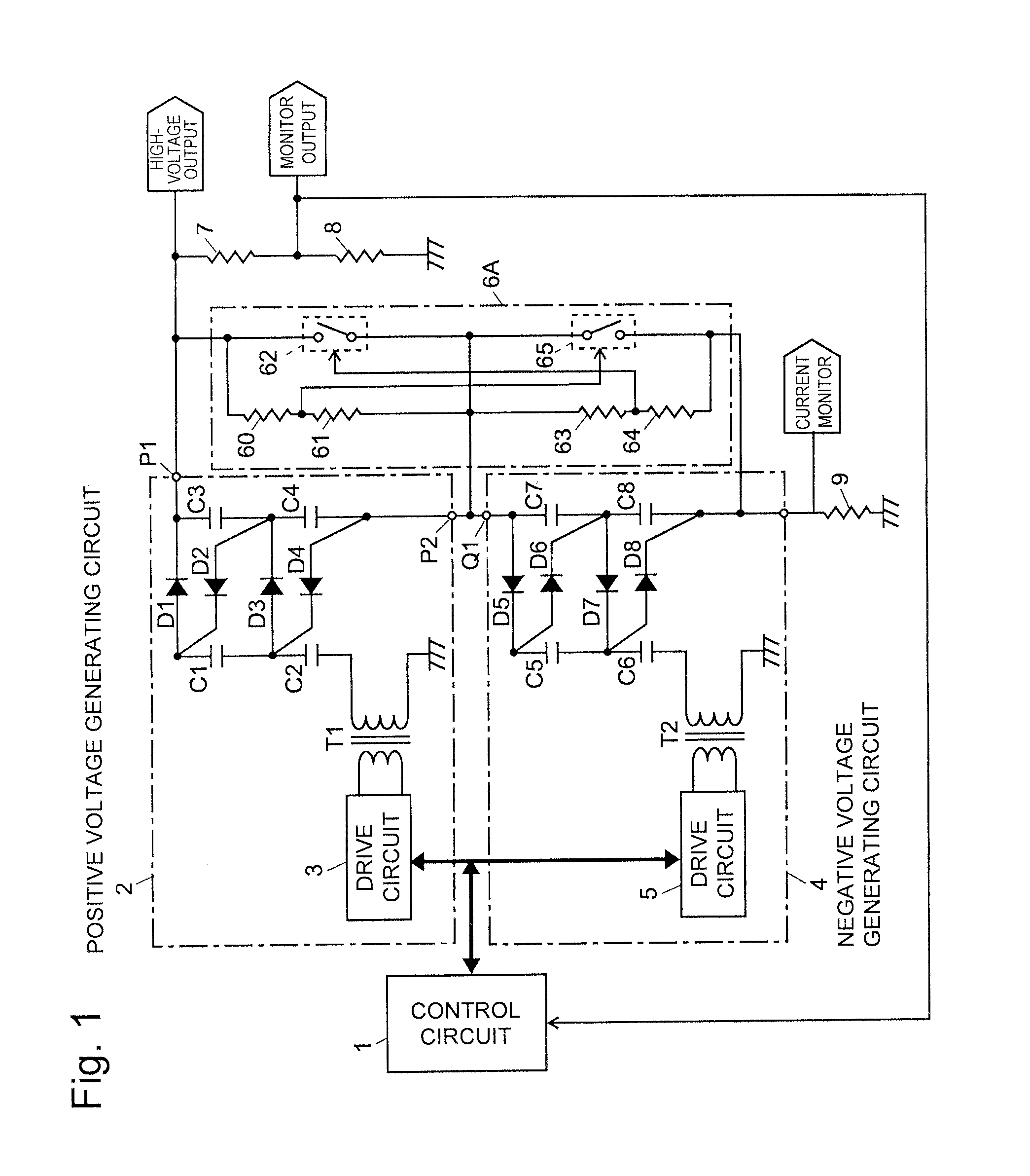
[0039]Hereinafter, one embodiment of a high-voltage power unit according to the present invention will be described in detail in reference to FIG. 1 through FIG. 3A and FIG. 3B. FIG. 1 is a schematic configuration diagram of principal part of the high-voltage power unit in the present embodiment. In FIG. 1, component members identical to those in the conventional high-voltage power unit illustrated in FIG. 7 are designated by identical reference numerals.

[0040]As is clear from comparison between FIG. 1 and FIG. 7, a control circuit 1, a positive voltage generating circuit 2 and a negative voltage generating circuit 4 which include drive circuits3 and 5, respectively, and a series connection circuit of resistors 7 and 8 are identical to each other. The high-voltage power unit of the present embodiment and the conventional unit are different in the following point. That is, in the conventional unit, the resistor 51 is connected between the output terminals P1 and P2 of the positive vo...


PUM


Abstract

An output terminal of a positive voltage generating circuit and an output terminal of a negative voltage generating circuit are connected in series, and an output terminal of the negative voltage generating circuit is connected to a ground via a resistor. A switching circuit and a series connection circuit of resistors are connected in parallel to each other between the output terminals of the positive voltage generating circuit and the negative voltage generating circuit. The switching circuit is on-off driven by a voltage signal taken from a junction point between the resistors, and the switching circuit is on-off driven by a voltage signal taken from a junction point between the resistors. Accordingly, when the polarity of an output voltage is switched, electric charges accumulated up to that point are discharged through the switching circuit of a voltage OFF-side polarity, so that the voltage quickly falls.

Description

TECHNICAL FIELD[0001]The present invention relates to a high-voltage power unit capable of switching the polarity of an output voltage between positive and negative, and to a mass spectrometer using the power unit.BACKGROUND ART[0002]Ion detectors including a combination of a conversion dynode and a secondary-electron multiplier are often used for detecting ions with high sensitivity in a mass spectrometer. In such an ion detector, a high voltage (±several [kV] to ±10[kV] for example) having a polarity opposite to that of the ions to be analyzed is applied to a conversion dynode for selectively detecting positive ions and negative ions. In a liquid chromatograph mass spectrometer, an ion source according to an electrospray ionization (ESI) method, for example, is used for vaporizing and ionizing a liquid sample. In such an ion source, a high voltage (±several [kV] for example) with the same polarity as that of the ions to be analyzed is applied to the tip of a nozzle for spraying th...

Claims


Application Information

Patent Timeline
Patent Type & Authority Applications(United States)
IPC IPC(8): H01J49/02H01J49/36H01J49/16H02M1/00
CPCH01J49/022H01J49/36H01J49/165H02M3/073H02M3/33507H02M7/103H02M1/0077H02M3/071
Inventor MIZUTANI, SHIRO
Owner SHIMADZU CORP
Why Eureka
Try Eureka