Technologies for Assigning Workloads Based on Resource Utilization Phases

a resource utilization and workload technology, applied in the field of cloud-based computing environment, can solve the problems of workload not being carried out, resource (e.g., a component, such as a processor, memory, communication circuitry, etc.) available in a compute node may become overloaded, and workload may not be carried ou

Active Publication Date: 2018-01-25
INTEL CORP
View PDF9 Cites 22 Cited by
  • Summary
  • Abstract
  • Description
  • Claims
  • Application Information

AI Technical Summary

Problems solved by technology

However, a resource (e.g., a component, such as a processor, memory, communication circuitry, etc.) available in a compute node may become overloaded if the server assigns multiple workloads that rely heavily that resource.
As a result, the overall performance of the compute node may be adversely affected, even when the other resources in the compute node are nearly idle.
A further challenge is that a workload may not consistently have the same resource utilization and may instead vary over time, making heavy use of one resource, and then transitioning to making heavy use of another resource.
As such, it may be difficult for an administrator or server to determine an assignment of workloads among the compute nodes that consistently provides high resource utilization without overloading any of the resources.

Method used


Image

  • Technologies for Assigning Workloads Based on Resource Utilization Phases
  • Technologies for Assigning Workloads Based on Resource Utilization Phases
  • Technologies for Assigning Workloads Based on Resource Utilization Phases

Examples


example 2

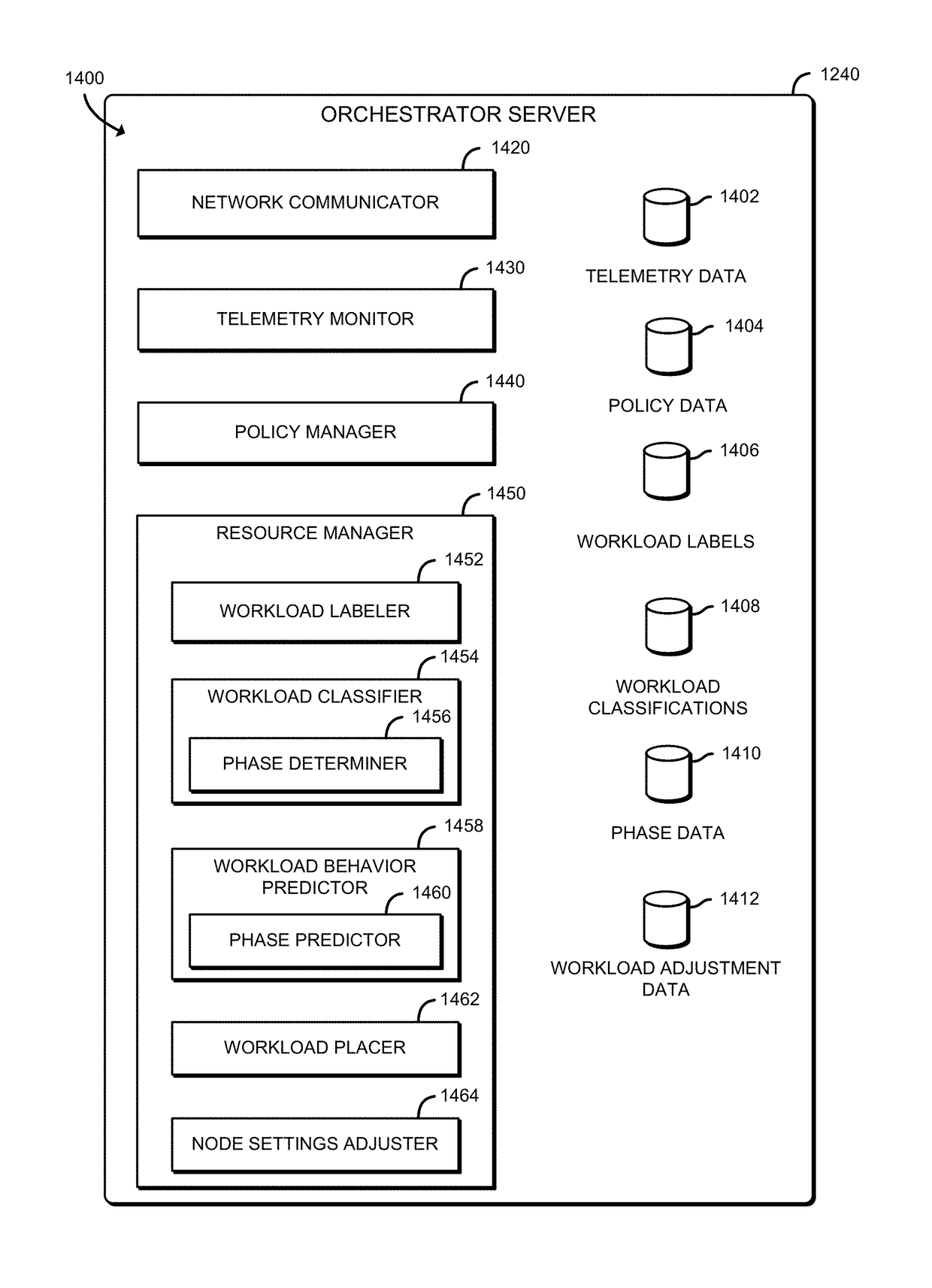
[0081 includes the subject matter of Example 1, and wherein to identify a historical resource utilization phase comprises to determine that the historical resource utilization phase is one of processor intensive, memory intensive, or network bandwidth intensive.

example 3

[0082 includes the subject matter of any of Examples 1 and 2, and wherein to determine a predicted resource utilization phase comprises to determine that the predicted resource utilization phase is one of processor intensive, memory intensive, or network bandwidth intensive.

example 4

[0083 includes the subject matter of any of Examples 1-3, and wherein to apply adjustments to the assignments of the workloads comprises to assign one of the workloads with a first type of predicted resource utilization phase and a second one of the workloads with a second type of predicted resource utilization phase to the same managed node for execution during the future time period.


PUM


Abstract

Technologies for assigning workloads based on resource utilization phases include an orchestrator server to assign a set of workloads to the managed nodes. The orchestrator server is also to receive telemetry data from the managed nodes and identify, as a function of the telemetry data, historical resource utilization phases of the workloads. Further, the orchestrator server is to determine, as a function of the historical resource utilization phases and as the workloads are performed, predicted resource utilization phases for the workloads, and apply, as a function of the predicted resources utilization phases, adjustments to the assignments of the workloads among the managed nodes as the workloads are performed.

Description

CROSS-REFERENCE TO RELATED APPLICATIONS[0001]The present application claims the benefit of U.S. Provisional Patent Application No. 62 / 365,969, filed Jul. 22, 2016, U.S. Provisional Patent Application No. 62 / 376,859, filed Aug. 18, 2016, and U.S. Provisional Patent Application No. 62 / 427,268, filed Nov. 29, 2016.BACKGROUND[0002]In a typical cloud based computing environment, a server may assign workloads to compute nodes in a network to perform services on behalf of a client. It is in the interest of the entity operating the cloud environment to maximize the resource utilization in each compute node to enable the cloud environment to provide the most performance with the available hardware. However, a resource (e.g., a component, such as a processor, memory, communication circuitry, etc.) available in a compute node may become overloaded if the server assigns multiple workloads that rely heavily that resource. As a result, the overall performance of the compute node may be adversely ...

Claims


Application Information

Patent Timeline
Patent Type & Authority Applications(United States)
IPC IPC(8): G06F9/50
CPCG06F2209/5019G06F9/505G06F15/161G06F13/4068G06F13/409G06F13/42H04L69/18H04L41/149H03M7/40H03M7/4081H03M7/4031H03M7/6005H04Q11/00H04L47/38Y02P90/30H03M7/6023G08C17/02G08C2200/00H04Q2213/13523H04L47/823H04L47/782H04L41/12H04L41/5019Y10S901/01H04L45/52H04Q2213/13527G06Q10/06G06Q10/06314G06Q10/087G06Q10/20G06Q50/04H04L49/15H04L49/357G06F9/5027G06F2209/483G06F9/4881G06F13/385H04L49/35H04Q1/09G06F3/061G06F3/0619G06F3/065G06F3/0659G06F3/067Y02D10/00Y10S901/30H04L41/40H04L45/02H04L47/83G06F3/0616G06F3/0631G06F3/0638G06F3/0647G06F9/3887G06F9/5016G06F9/5072G06F2209/5022G06F2212/1024G06F2212/1041H04L43/16H04L47/24H04L67/1004H04L67/1034H04L67/1097H04L67/12H04Q11/0071H04Q2011/0041H04Q2011/0052H04Q2011/0073H04Q2011/0079H04Q2011/0086H05K5/0204H05K7/1485H05K7/1489H05K7/1491H05K2201/066H05K2201/10121H05K2201/10159H04L43/08H04W4/80G06F16/9014H04B10/25891G02B6/3882G02B6/3893G02B6/3897G02B6/4292G02B6/4452G06F1/183G06F1/20G06F3/0613G06F3/0625G06F3/064G06F3/0653G06F3/0655G06F3/0664G06F3/0665G06F3/0673G06F3/0679G06F3/0683G06F3/0688G06F3/0689G06F8/65G06F9/30036G06F9/4401G06F9/544G06F12/109G06F12/1408G06F13/1668G06F2212/1008G06F2212/1044G06F2212/152G06F2212/202G06F2212/401G06F2212/402G06F2212/7207G11C5/02G11C7/1072G11C11/56G11C14/0009H03M7/3086H03M7/4056H04B10/25H04L41/145H04L43/065H04L43/0817H04L43/0876H04L43/0894H04L49/00H04L49/25H04L49/45H04L67/02H04L67/306H04L69/04H04L69/329H04Q11/0003H04Q2011/0037H05K7/1442H05K2201/10189Y04S10/50Y04S10/52H04L61/00H04L67/51H04J14/00G06F3/0658H05K7/1498H04L41/147H04L67/1008H04L41/0813H04L67/1029H04L41/0896H04Q11/0005G06F3/0611H04L41/082H04L67/34H04L67/1012B25J15/0014B65G1/0492H05K7/1492H05K7/20736H04L49/555H04L67/10H04Q11/0062H04W4/023G06F13/4282H05K1/181H05K7/2039H05K7/20709H05K7/1418H05K7/1461G05D23/1921G05D23/2039H05K7/20727H05K7/20745H05K7/20836G06F9/5044H04L47/805H05K1/0203H05K7/1487H04Q1/04G06F12/0893H03M7/3084H05K13/0486G06F13/1694G11C5/06H03M7/30H05K7/1421H05K7/1422H05K7/1447G06F11/141G06F11/3414G06F12/0862G06F15/8061H04L47/765H04L67/1014G06F9/5077G06F12/10G06F13/161G06F13/4022G07C5/008H04L12/2809H04L41/024H04L9/0643H04L9/14H04L9/3247H04L9/3263H04L47/82H04L41/046
Inventor BALLE, SUSANNE M.KHANNA, RAHULAHUJA, NISHIGANGULI, MRITTIKA
Owner INTEL CORP
Why Eureka
Try Eureka