Case for electric motor

a technology for electric motors and cases, applied in the direction of supporting/enclosed/casings, dynamo-electric machines, and control/drive circuits, etc., can solve the problems of occupying a larger space, and affecting the cooling performance of electric motors. , to achieve the effect of reducing size and weigh

Active Publication Date: 2018-01-25
LG MAGNA E POWERTRAIN CO LTD
View PDF7 Cites 25 Cited by
  • Summary
  • Abstract
  • Description
  • Claims
  • Application Information

AI Technical Summary

Benefits of technology

[0023]Therefore, an aspect of the present invention is to provide a case for an electric motor, capable of reducing size and weight by allowing a motor and an inverter to be cooled through a single cooling flow path.
[0024]Another aspect of the present invention is to provide a case for an electric motor, capable of facilitating easier fabrication and installation.
[0033]In accordance with one embodiment disclosed herein, the circuit component and the circuit component mounting portion may be provided with a circuit component vibration suppressing unit detachably coupled in the axial direction to suppress a generation of vibration from the circuit component.

Problems solved by technology

However, in the related art electric motor, a cooling fluid flow path in a spiral shape is formed along a periphery of the case, and accordingly, a heat exchange area between the cooling fluid and the case is relatively small, which causes a limit in improving cooling performance.
When the temperature rises excessively, the inverter may cause an error or a functional deterioration and / or a functional stop.
Further, when the sizes of the motor, the inverter, and the cooling unit are increased, they occupy a larger space when mounted in a vehicle.
In addition, since the cooling unit of the electric motor and the cooling unit of the inverter are fabricated separately, a relatively long time and much effort are required to fabricate and install them.
Since the weights of the electric motor, the inverter, and the cooling unit are increased, a battery consumption of the vehicle is increased, thereby reducing a traveling (driving) distance of the vehicle.
Furthermore, the battery consumption of the vehicle is accelerated and a charging period of the battery is shortened accordingly.
This causes an increase in a waiting time for charging, thereby bringing about inconvenience in driving the vehicle when charging is required.

Method used


Image

  • Case for electric motor
  • Case for electric motor
  • Case for electric motor

Examples


Embodiment Construction

[0072]Description will now be given in detail according to exemplary embodiments disclosed herein, with reference to the accompanying drawings. For the sake of brief description with reference to the drawings, the same or equivalent components may be provided with the same or similar reference numbers, and description thereof will not be repeated. A singular representation may include a plural representation unless it represents a definitely different meaning from the context. In describing the present invention, the detailed description will be omitted when a specific description for publicly known technologies to which the invention pertains is judged to obscure the gist of the present invention. Also, it should be noted that the accompanying drawings are merely illustrated to easily explain the spirit of the invention, and therefore, they should not be construed to limit the spirit of the invention by the accompanying drawings.

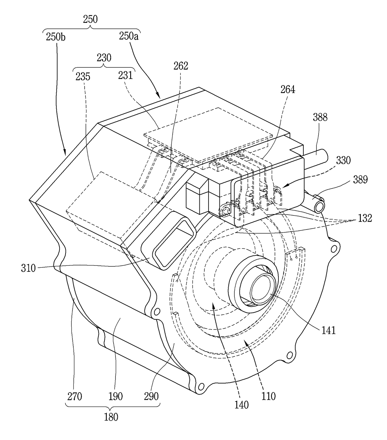
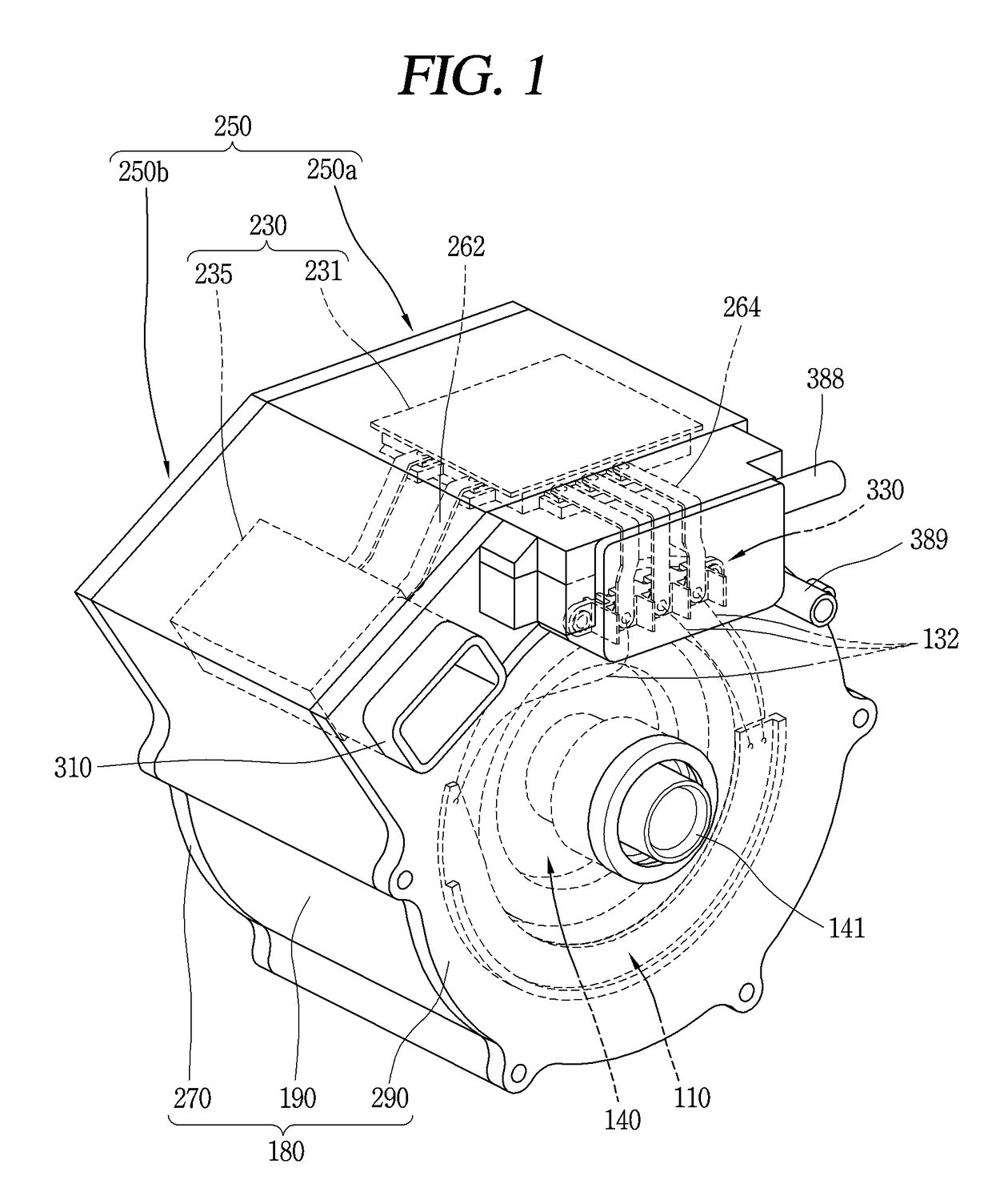
[0073]FIG. 1 is a perspective view of an electric mot...


PUM


Abstract

A case for an electric motor includes a case body provided with an inner case and an outer case together forming a cooling fluid flow path penetratingly formed in an axial direction of the case body, and a circuit component mounting portion protruding from an outer surface of the outer case to mount a circuit component such that the circuit component is cooled by cooling fluid. Case covers are coupled to both end portions of the case body so that the electric motor and the circuit component can be simultaneously cooled by the single cooling fluid flow path. In this way, a separate circuit component case for mounting the circuit component can be excluded, thereby reducing a size and weight of the case.

Description

CROSS-REFERENCE TO RELATED APPLICATION[0001]Pursuant to 35 U.S.C. §119(a), this application claims the benefit of an earlier filing date of and the right of priority to U.S. Provisional Application No. 62 / 364,840, filed on Jul. 20, 2016 and Korean Application No. 10-2017-0068620, filed on Jun. 1, 2017, the entire contents of both of which are hereby incorporated by reference herein in their entireties.BACKGROUND OF THE INVENTION1. Field of the Invention[0002]The present invention relates to a case for an electric motor.2. Background of the Invention[0003]As is well known, an electric motor is a device that converts electric energy into kinetic energy.[0004]Such electric motors are classified into a direct-current (DC) motor and an alternating current (AC) motor according to a type of power source.[0005]The electric motor includes a stator and a rotor arranged to be movable relative to the stator.[0006]The rotor is rotatably provided with a predetermined gap from the stator.[0007]The...

Claims


Application Information

Patent Timeline
Patent Type & Authority Applications(United States)
IPC IPC(8): H02K5/20H02K5/22H02K5/24H02K9/00
CPCH02K5/20H02K5/24H02K5/225H02K9/005H02K11/33H02K5/203H02K2211/03H02K9/16H05K7/20263H05K7/20272H02K9/19H02K5/18H02K9/00
Inventor JUNG, SEUNGMOKWAK, TAEHEEKIM, HYEONGJUN
Owner LG MAGNA E POWERTRAIN CO LTD
Why Eureka
Try Eureka