
Projectile, and warhead assembly and deployment system therfor

Active Publication Date: 2018-02-01
ISRAEL AEROSPACE IND
View PDF1 Cites 0 Cited by
  • Summary
  • Abstract
  • Description
  • Claims
  • Application Information

AI Technical Summary

Benefits of technology

The deployment system described in this patent allows for an expansion member to be placed between two modules, which expands to push the modules apart and create space between them. Additionally, the system improves the distance between the main warhead and the tip of the projectile, making it more efficient than older systems.

Problems solved by technology

At distances greater than the standoff spacing, the metallic jet can break up before reaching the target and is thus less effective, while at distances closer than the stand-off spacing there is insufficient time for the metallic jet to form properly before reaching the target.
In many such cases, it would not be physically possible to store and / or load a projectile having the desired warhead spacing and / or standoff spacing.

Method used


Image

  • Projectile, and warhead assembly and deployment system therfor
  • Projectile, and warhead assembly and deployment system therfor
  • Projectile, and warhead assembly and deployment system therfor

Examples


Embodiment Construction

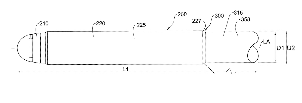
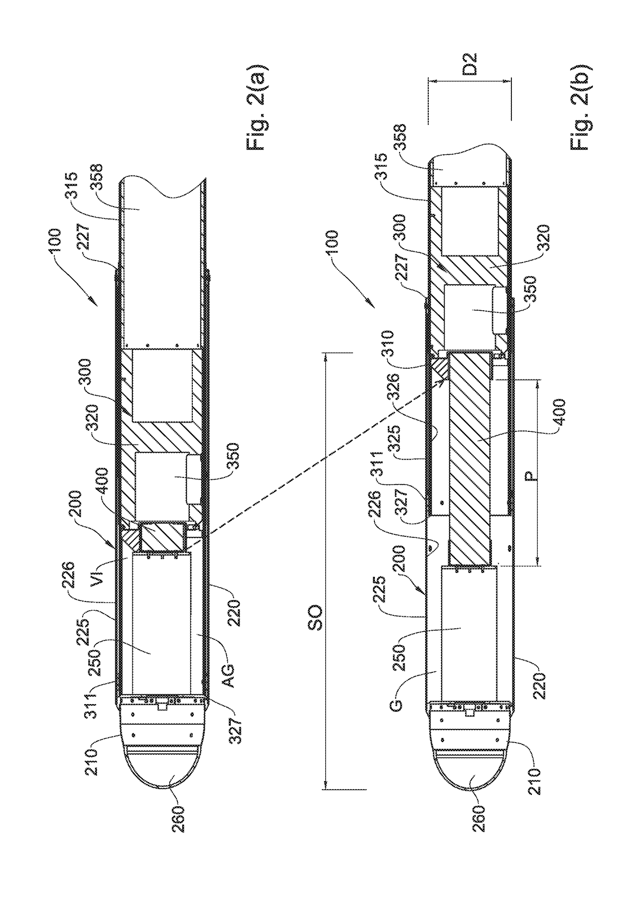
[0115]Referring to FIGS. 2(a), 2(b), 3(a) and 3(b), a warhead assembly according to a first example of the presently disclosed subject matter, generally designated 100, comprises a forward module 200 and an aft module 300, and a deployment system 400.

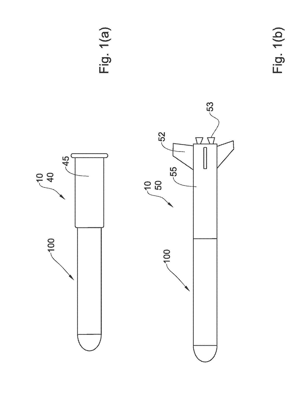
[0116]Referring to FIG. 1(a), the warhead assembly 100 can be configured as part of a projectile 10 in the form of shell 40, to be fired from breech loaded gun barrel, for example, of a combat tank or of a self propelled gun or of an artillery piece for example, the shell 40 comprising cartridge case 45 housing a suitable propellant (not shown). Alternatively, and referring to FIG. 1(b), the warhead assembly 100 can be configured as part of a projectile 10 in the form of a rocket or missile 50, to be fired from a suitable rocket launcher, and comprising a body section 55 including fins 52, for example, and propulsion system 53.

[0117]In any case, the forward module 200 comprises a precursor warhead 250, which in this example is configure...


PUM


Abstract

A warhead assembly is provided for a projectile includes a forward module having a precursor warhead, and an aft module including a main warhead. The warhead assembly includes a deployment system for selectively deploying the warhead assembly from a retracted configuration to a deployed configuration, at predetermined conditions, to thereby provide a longitudinal displacement between the forward module and the aft module. The deployment system includes an expansion member accommodated between the forward module and the aft module, and configured for being longitudinally expanded under the predetermined conditions to thereby increase a longitudinal dimension of the expansion member and thereby urge the forward module and the aft module away from one another to provide said longitudinal displacement. A corresponding deployment system and projectile are also provided.

Description

TECHNOLOGICAL FIELD[0001]The presently disclosed subject matter relates to projectiles, in particular projectiles having a precursor warhead and a main warhead in tandem arrangement.BACKGROUND ART[0002]References considered to be relevant as background to the presently disclosed subject matter are listed below:[0003]U.S. Pat. No. 4,770,369[0004]U.S. Pat. No. 4,848,238[0005]U.S. Pat. No. 4,944,226[0006]U.S. Pat. No. 5,007,347[0007]U.S. Pat. No. 5,460,676[0008]U.S. Pat. No. 5,744,746[0009]U.S. Pat. No. 6,109,185[0010]U.S. Pat. No. 7,118,072[0011]Acknowledgement of the above references herein is not to be inferred as meaning that these are in any way relevant to the patentability of the presently disclosed subject matter.BACKGROUND[0012]Some types of projectiles are designed with tandem warheads, which include a precursor warhead (sometimes also referred to as a tip charge) in tandem arrangement with a main warhead, i.e., the precursor warhead is longitudinally spaced from the main war...

Claims


Application Information

Patent Timeline
IPC IPC(8): F42B12/18F42B15/01
CPCF42B12/18F42B15/01F42B12/625
Inventor OSDON, TALMARGOLIS, HERMANTIRASPOLSKI, ILAN
Owner ISRAEL AEROSPACE IND
Learn More