Integral prefabricated steel plate composite beam structure and construction method

A technology of overall prefabrication and prefabrication of beams, applied in bridges, bridge construction, bridge parts, etc., can solve problems such as large workload on site, difficult construction, and difficult quality control.

Active Publication Date: 2020-10-23
HUNAN PROVINCIAL COMM PLANNING SURVEY & DESIGN INST CO LTD
View PDF8 Cites 0 Cited by
  • Summary
  • Abstract
  • Description
  • Claims
  • Application Information

AI Technical Summary

Problems solved by technology

[0004] For conventional steel plate composite girder bridges, steel longitudinal girders and concrete bridge decks are processed and manufactured separately. After the steel girders are erected and connected, the prefabricated bridge decks are installed, and finally wet joint operations are performed. This method has the following disadvantages: 1. Steel girders and bridge decks The self-weight of the panel is borne by the steel girder alone, and the composite girder only bears small loads such as bridge deck pavement and vehicle load, which fails to give full play to the advantages of the composite structure. Further, because the steel longitudinal girder bears most of the load alone, the Steel girders with a relatively high height need to be used, and the line position needs to be raised when the net height is limited. At the same time, vertical and horizontal stiffeners need to be installed on taller steel longitudinal beams, which increases the amount of steel structure processing and bridge construction costs; 2. The construction sequence of erecting steel girders first and then installing bridge decks cannot use bridge erecting machines with low cost and strong adaptability. Generally, gantry cranes need to be arranged along the line for hoisting and installation, which not only increases investment but also limits conventional steel plate composite girders In areas with complex terrain, especially in mountainous areas; 3. When erecting steel beams, it is necessary to complete the connection of multi-span (or multi-segment) steel beams to form continuous beams. Set up temporary piers and complete the connection of steel longitudinal girders at high altitude. The construction is difficult, the quality controllability is poor, and the cost of measures is high; 4. Limited by the hoisting capacity and structural form of equipment, bridge decks are generally prefabricated in longitudinal The size is small, resulting in a large number of wet joints running through the bridge deck, the workload on site is large, and the quality is not easy to control, which is the weak point of the structure

Method used


Image

  • Integral prefabricated steel plate composite beam structure and construction method
  • Integral prefabricated steel plate composite beam structure and construction method
  • Integral prefabricated steel plate composite beam structure and construction method

Examples


Embodiment 1

[0038] Figure 1 to Figure 9 An embodiment of the integrally prefabricated steel plate composite girder of the present invention is shown.

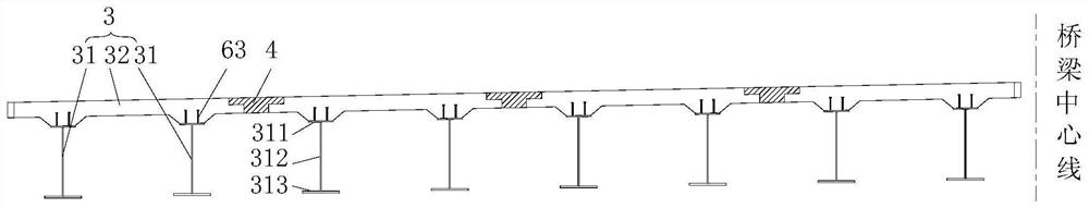
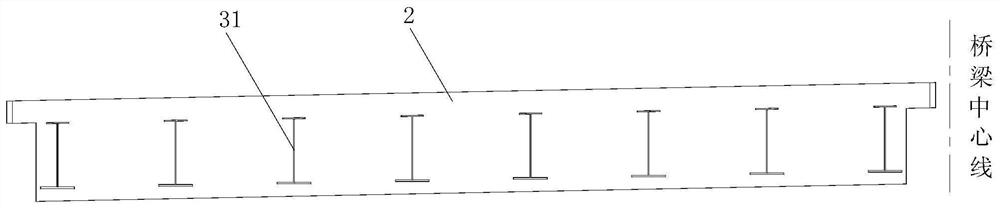
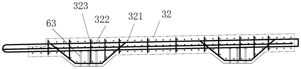
[0039] Specific as figure 1 As shown, the steel longitudinal beam 31 (also known as the steel main beam) is 2.1m apart, and adopts a standard I-shaped section, including a steel longitudinal beam top plate 311, a steel longitudinal beam web plate 312, and a steel longitudinal beam bottom plate 313. The steel longitudinal beam 31 Beam height 1180mm (that is to say the vertical dimension of steel longitudinal beam 31), wherein steel longitudinal beam top plate 311 is 400mm wide and 16mm thick; steel longitudinal beam web 312 is 1134mm high and 18mm thick; steel longitudinal beam bottom plate 313 is 600mm wide and 30mm thick. Concrete bridge deck 32 adopts common concrete, and vertical common steel bar and horizontal common steel bar are arranged in concrete bridge deck 32 (specifically as Figure 4 and Figure 5 As shown), the concrete ...

Embodiment 2

[0044] The overall construction method of this implementation example is as follows:

[0045] Firstly manufacture the steel girder segments and transport them to the prefabrication site, complete the splicing of each steel girder 31 on the pedestal, then prefabricate the bridge deck on the top of the two steel longitudinal girders 31, demould and store after the concrete strength reaches the design strength Then the prefabricated girders are hoisted to the installed bridge deck by the gantry crane in the girder yard, and the beam transport vehicle uses the existing bridge deck to transport the prefabricated beams to the erection position, and the prefabricated composite beams are erected hole by hole through the bridge erecting machine. After the whole bridge is erected, The longitudinal wet joint 4 is poured, and finally the beam at the continuous pier is poured to complete the system conversion from simply supported to continuous.

[0046] The construction method for the π-s...


PUM


Abstract

An integral precast steel plate composite beam structure comprises two steel longitudinal beams and a concrete bridge deck arranged on the steel longitudinal beams, wherein the bridge deck extends transversely to the outside of the two steel longitudinal beams, the steel longitudinal beams are connected with the bridge deck, the transversely adjacent bridge decks are connected through a longitudinal wet joint, and the side fulcrum cast-in-situ cross beams are connected with the integral precast beams. The construction method comprises the following steps: manufacturing each steel beam and completing the splicing of each steel beam; Erecting formwork, laying reinforcement and pouring bridge deck concrete; Lift it to the installed bridge deck, transport it to the erection position by beam truck, and erect it step by step through the bridge erection machine; Pouring longitudinal wet joint; Connect the cast-in-situ beam with the integral precast beam, and then cast the beam to complete thesystem transformation from simple support to continuous support. Anti-collision fence in the cast-in-place beam area at the construction side fulcrum. The invention can give full play to steel. The advantages of concrete composite structure, strong mechanical capacity, convenient construction, can reduce the cost of the project.

Description

technical field [0001] The invention relates to the technical field of bridge engineering, in particular to an integrally prefabricated steel plate composite girder and a construction method, which are suitable for medium and small-span bridges with a single-hole span ranging from 5m to 40m. Background technique [0002] Small and medium-span bridges refer to bridges with a single-hole span between 5m and 40m. Because of their mature design and construction technology, simple structure, and low cost, they can be used in highways, approach bridges of large bridges, or in urban viaducts and interchange systems. In construction, they all occupy a huge proportion. [0003] Traditional small and medium-span bridges are generally concrete girder bridges. Although the design and construction technology is mature and the cost is low, there are also disadvantages such as long construction period and self-heavy weight; steel girder bridges can greatly shorten the construction period a...

Claims


Application Information

Patent Timeline
Patent Type & Authority Patents(China)
IPC IPC(8): E01D19/00E01D19/12E01D21/00
CPCE01D19/00E01D19/125E01D21/00
Inventor 贺耀北向建军杨沪湘刘榕李瑜伍英薛梦归刘婷婷
Owner HUNAN PROVINCIAL COMM PLANNING SURVEY & DESIGN INST CO LTD
Why Eureka
Try Eureka