Accurate non-isolated high voltage dc-dc feedback

a dc-dc feedback and input and output voltage technology, applied in the field of dc-dc converter design, control and operation, can solve the problems of introducing expense and error in > contributing error to the output voltage feedback, and the existing solution for controlling a dc-dc voltage converter with non-isolated input and output voltage is extremely difficul

Active Publication Date: 2018-02-01
NXP USA INC
View PDF3 Cites 12 Cited by
  • Summary
  • Abstract
  • Description
  • Claims
  • Application Information

AI Technical Summary

Problems solved by technology

Conventional power supply solutions employing DC-DC voltage converter topologies (e.g., buck or buck-boost converters) which use the output to regulate the converter performance may use expensive components (e.g., opto-coupler or transformer circuits) to feedback the DC-DC converter output voltage to a floating DC-DC voltage converter.
While feedback solutions have been proposed which do not require expensive feedback components, such solutions often introduce error into the feedback signal and / or otherwise require additional components and circuitry which can also introduce expense and error in the output voltage feedback.
However, the compensation diode arrangement of the first and second diodes D1, D8 can contribute error to the output voltage feedback.
As seen from the foregoing, the existing solutions for controlling a DC-DC voltage converter having non-isolated input and output voltages are extremely difficult at a practical level by virtue of introducing circuit component complexity and expense as well as feedback error.

Method used


Image

  • Accurate non-isolated high voltage dc-dc feedback
  • Accurate non-isolated high voltage dc-dc feedback
  • Accurate non-isolated high voltage dc-dc feedback

Examples


Embodiment Construction

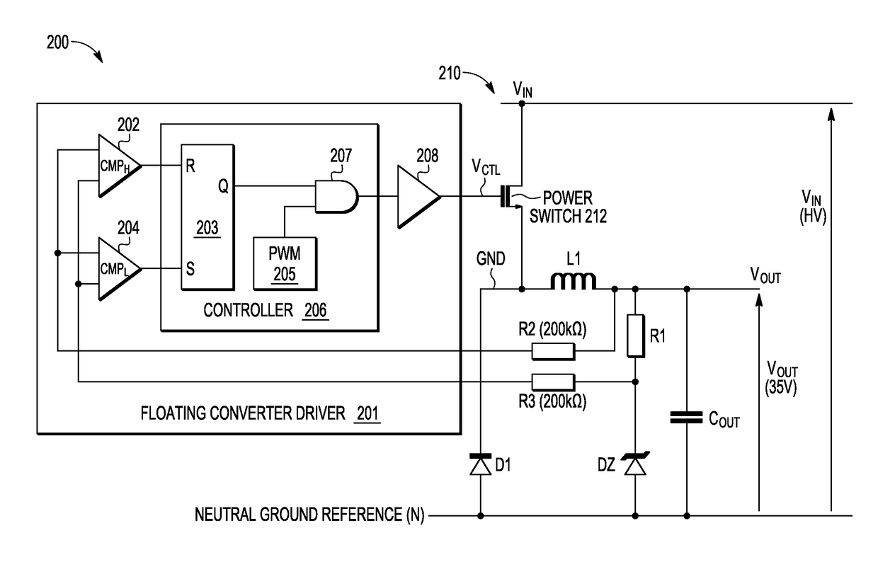
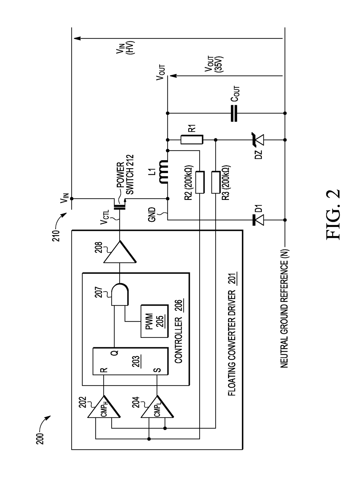
[0012]A non-isolated high voltage DC-DC converter circuit and method are disclosed which use a pulse width modulator (PWM) circuit and power transistor to generate the converter output voltage across an output resistor (e.g., R1=10KΩ) and zener diode (e.g., DZ) connected in series between the converter output and neutral ground reference (N). To prevent distortions caused by the freewheeling diode in the voltage feedback path, the disclosed converter provides output voltage regulation by including a feedback path with a pair of relatively large resistive elements (e.g., over 200 kΩ) connected across the output resistor R1 to generate high and low signals (SH, SL) which are fed back as inputs to a pair of upper and lower comparator drivers (CMPH, CMPL) in a floating converter driver. During commuting operations of the PWM circuit, the upper comparator driver CMPH in the floating converter reads the converter output voltage across the pair of relatively large resistive elements only w...


PUM


Abstract

A method and apparatus for regulating a non-isolated high voltage converter applies a PWM signal to a power transistor that couples an input voltage to a floating ground node to charge an inductor and generate an output voltage which is measured with a first floating comparator to disable the PWM signal upon detecting a high threshold output voltage, the first floating comparator having inputs connected across first and second resistive elements to measure a voltage across a feedback resistor connected in series with a diode between the output voltage and a neutral ground reference. Subsequently, the output voltage is measured with a second floating comparator to enable the PWM signal upon detecting a low threshold output voltage, where the second floating comparator has inputs connected across the first and second resistive elements to measure the feedback voltage across the feedback resistor.

Description

BACKGROUND OF THE INVENTIONField of the Invention[0001]The invention relates generally to the field of semiconductor devices. In one aspect, the present invention relates to the design, control, and operation of a DC-DC converter having non-isolated input and output voltages.Description of the Related Art[0002]There are many applications which use non-isolated power supplies to furnish low output power required to run microcontrollers, motors, LED displays, automotive devices, relays, AC switches, and the like. Conventional power supply solutions employing DC-DC voltage converter topologies (e.g., buck or buck-boost converters) which use the output to regulate the converter performance may use expensive components (e.g., opto-coupler or transformer circuits) to feedback the DC-DC converter output voltage to a floating DC-DC voltage converter. While feedback solutions have been proposed which do not require expensive feedback components, such solutions often introduce error into the ...

Claims


Application Information

Patent Timeline
Patent Type & Authority Applications(United States)
IPC IPC(8): H02M3/156H02M1/08
CPCH02M3/156H02M2001/0009H02M1/08H02M3/158H02M3/1582H02M1/0009
Inventor SICARD, THIERRY
Owner NXP USA INC
Why Eureka
Try Eureka