Feed device for reinforcing fiber material and method for cutting reinforcing fiber material by using the feed device

Active Publication Date: 2018-02-08
TSUDAKOMA KOGYO KK
View PDF1 Cites 6 Cited by
  • Summary
  • Abstract
  • Description
  • Claims
  • Application Information

AI Technical Summary

Benefits of technology

[0023]Moreover, the cutting mechanism is configured such that the cutter roll (blade portion) moved in the axial direction while the cutter roll cuts the reinforcing fiber material. When the reinforcing fiber material is cut, the contact part of the blade portion with respect to the reinforcing fiber material is displaced toward the side in the moving direction of the reinforcing fiber material. Accordingly, since the cutter roll having the linearly formed blade portion is provided as described above, even if the displacement direction of the blade portion along with the rotation of the roll body and the movement direction of the reinforcing fiber material are markedly different from each other, the reinforcing fiber material can be reliably cut, and the positional shift in the width direction of the reinforcing fiber material caused by the contact with the blade portion can be prevented as much as possible.
[0024]That is, in a view in the thickness direction of the reinforcing fiber material, the direction in which the blade portion is displaced along with the rotation of the roll body is the direction perpendicular to the axial direction. In contrast, when the reinforcing fiber material is cut, the blade portion is also displaced in the axial direction. By combining b

Problems solved by technology

In this case, the protruding portions have to be cut in a later process, the cut portions are thrown away, and the reinforcing fiber material unfortunately wastefully consumed.
When the moving reinforcing fiber material is cut, in the cutting mechanism configured to cut the reinforcing fiber material by advancing and retracting the cutter to and from the reinforcing fiber material as described above, the reinforcing fiber material may not be reliably (completely) cut, or the cutter may interfere with the movement of the reinforcing fiber material.
However, there may be some problems when the blade portion of the cutter roll is spirally formed in the cutting mechanism that cuts the reinforcing fiber material by the cutter roll and the receiving member.
For example, such a cutter roll has to have a blade portion to cut a sheet material at a desirable cutting angle as described above; however, it may be difficult t

Method used


Image

  • Feed device for reinforcing fiber material and method for cutting reinforcing fiber material by using the feed device
  • Feed device for reinforcing fiber material and method for cutting reinforcing fiber material by using the feed device
  • Feed device for reinforcing fiber material and method for cutting reinforcing fiber material by using the feed device

Examples


Example

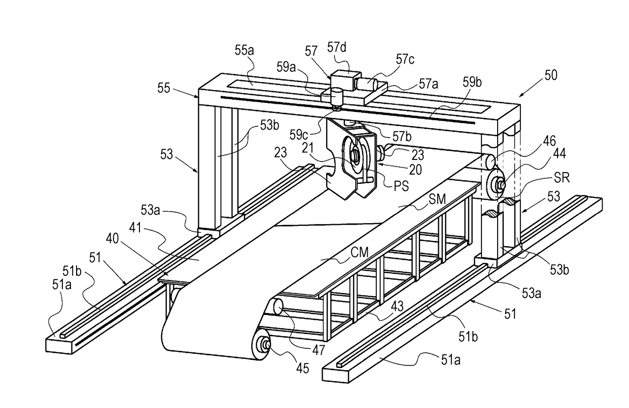
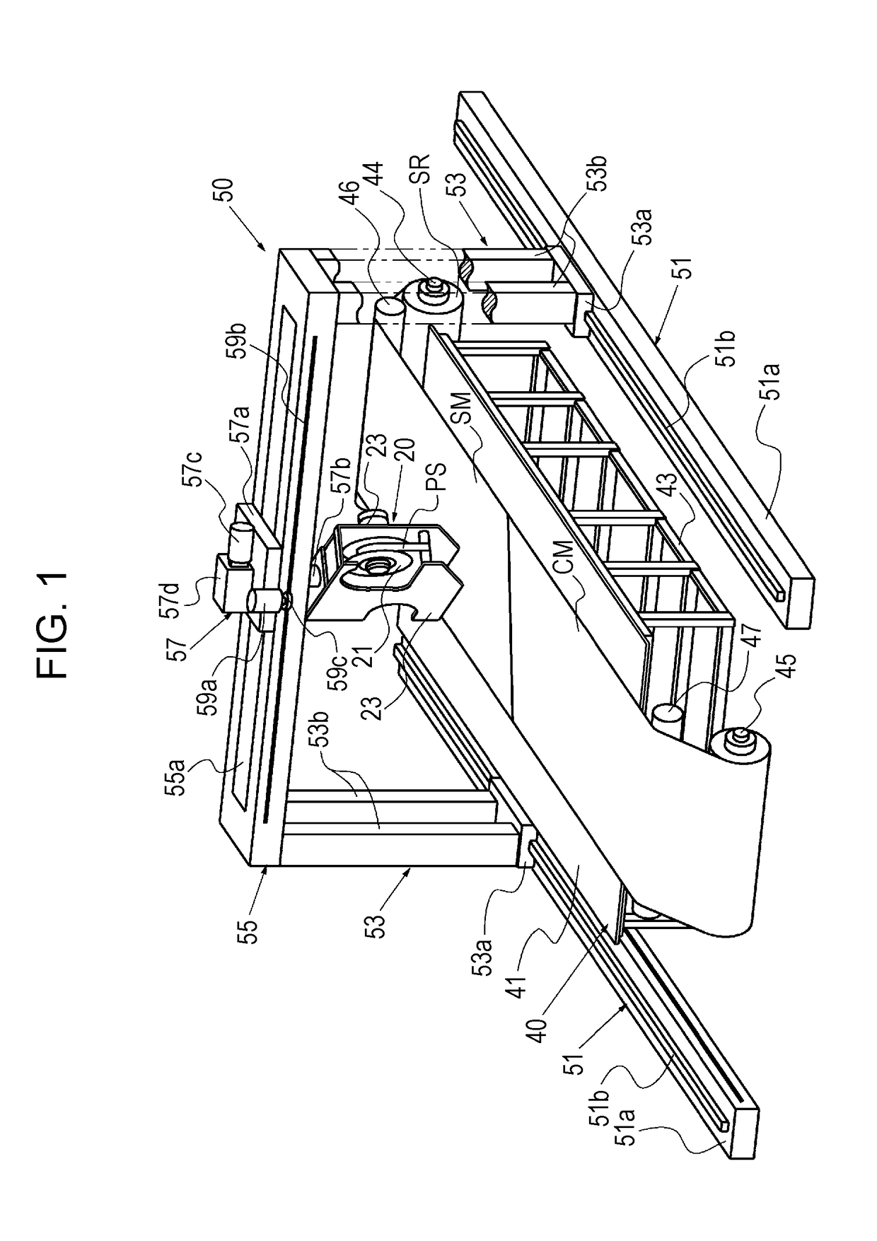
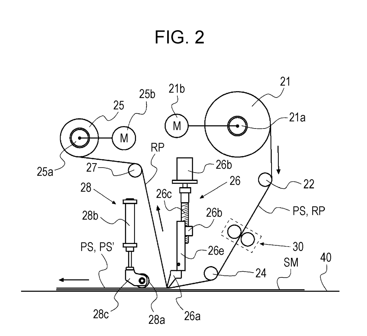
[0031]Hereinafter, for a feed device for a reinforcing fiber material according to the present invention and a method for cutting the reinforcing fiber material by using the feed device, an embodiment (exemplary embodiment) is described. An exemplary embodiment (this exemplary embodiment) described below is an example, in which the feed device is mounted on an automatic lay-up machine that is illustrated in FIGS. 1 and 2, and that lays up a sheet-shaped reinforcing fiber material fed from the feed device on a table. Also, in this exemplary embodiment, it is assumed that the reinforcing fiber material is a sheet material (prepreg sheet) made of a prepreg obtained by impregnating carbon fibers serving as reinforcing fibers with a thermoplastic resin such as epoxy resin serving as a matrix resin. Moreover, it is assumed that the automatic lay-up machine lays up a prepreg sheet piece on a sheet material such as a film serving as a support member fed on the table, at an angle with respec...


PUM

PropertyMeasurementUnit
Circumferenceaaaaaaaaaa

Abstract

A cutting mechanism includes a cutter roll and a rotational driving mechanism for rotationally driving the cutter roll. The cutter roll has a roll body and a blade portion protruding from a peripheral surface of the roll body. The blade portion is formed at a same position on a circumference of the roll body and extends in an axial direction of the roll body. The cutter roll is arranged so that the axial direction is at a predetermined angle with respect to a pull-out direction of the reinforcing fiber material. The cutting mechanism further includes a slide mechanism that displaces cutter roll in the axial direction toward a side in the pull-out direction of the reinforcing fiber material at least when the reinforcing fiber material is cut.

Description

BACKGROUND OF THE INVENTION1. Field of the Invention[0001]The present invention relates to a feed device for an elongated sheet-shaped reinforcing fiber material made of a reinforcing fiber and a matrix resin, the device including a raw-material roll formed by winding the reinforcing fiber material, and a cutting mechanism for cutting the reinforcing fiber material pulled out from the raw-material roll and hence cutting off a reinforcing fiber material piece from the reinforcing fiber material; and a method for cutting the reinforcing fiber material by using the feed device.2. Description of the Related Art[0002]A feed device for a reinforcing fiber material like the one described above may be, for example, a device disclosed in Japanese Unexamined Patent Application Publication No. 2015-217540. The feed device disclosed in Japanese Unexamined Patent Application Publication No. 2015-217540 is a device for feeding a prepreg of an automatic lay-up machine for laying up the prepreg, se...

Claims


Application Information

Patent Timeline
IPC IPC(8): B32B37/10B29C70/50B30B5/06B29C63/02
CPCB32B37/1036B29C63/024B29C63/0021B30B5/062B29C70/504B29C70/388B29C70/545B26D1/405B29C2793/0027B29C2793/0081B29C70/50B26D7/2628Y10T156/1077Y10T156/1085Y10T156/1098
Inventor NISHIMURA, ISAOFUTAKUCHI, MITSUNOBU
Owner TSUDAKOMA KOGYO KK
Why Eureka
Try Eureka