Rotating cylinder type compressor
a rotating cylinder type, compressor technology, applied in the direction of machines/engines, rotary/oscillating piston pump components, liquid fuel engines, etc., can solve the problems of noise and vibration, and it is difficult to acquire the above-mentioned downsizing effect as a whole compressor, so as to increase the discharge capacity of the rotating cylinder type compressor and increase the volume of the compression chamber.
- Summary
- Abstract
- Description
- Claims
- Application Information
AI Technical Summary
Benefits of technology
Problems solved by technology
Method used
Image
Examples
first embodiment
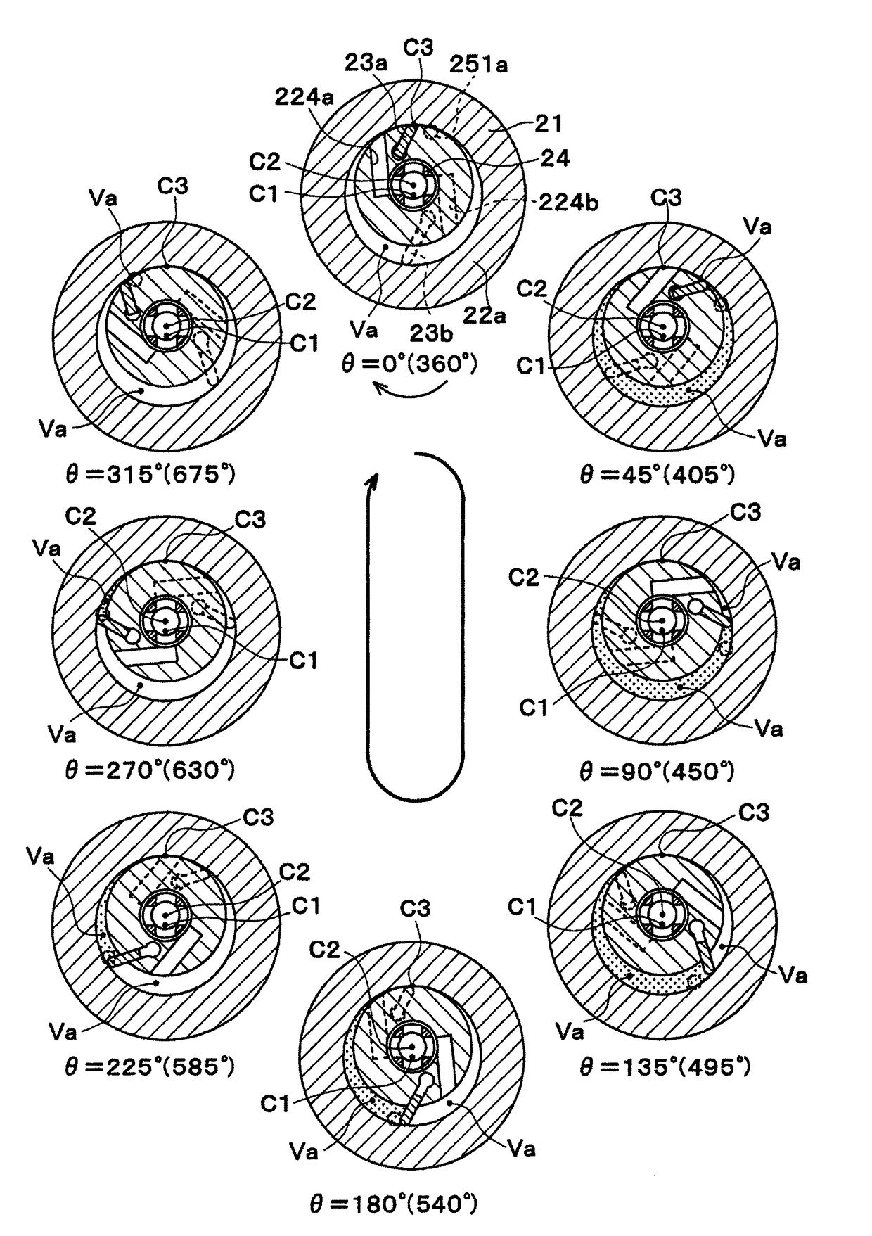
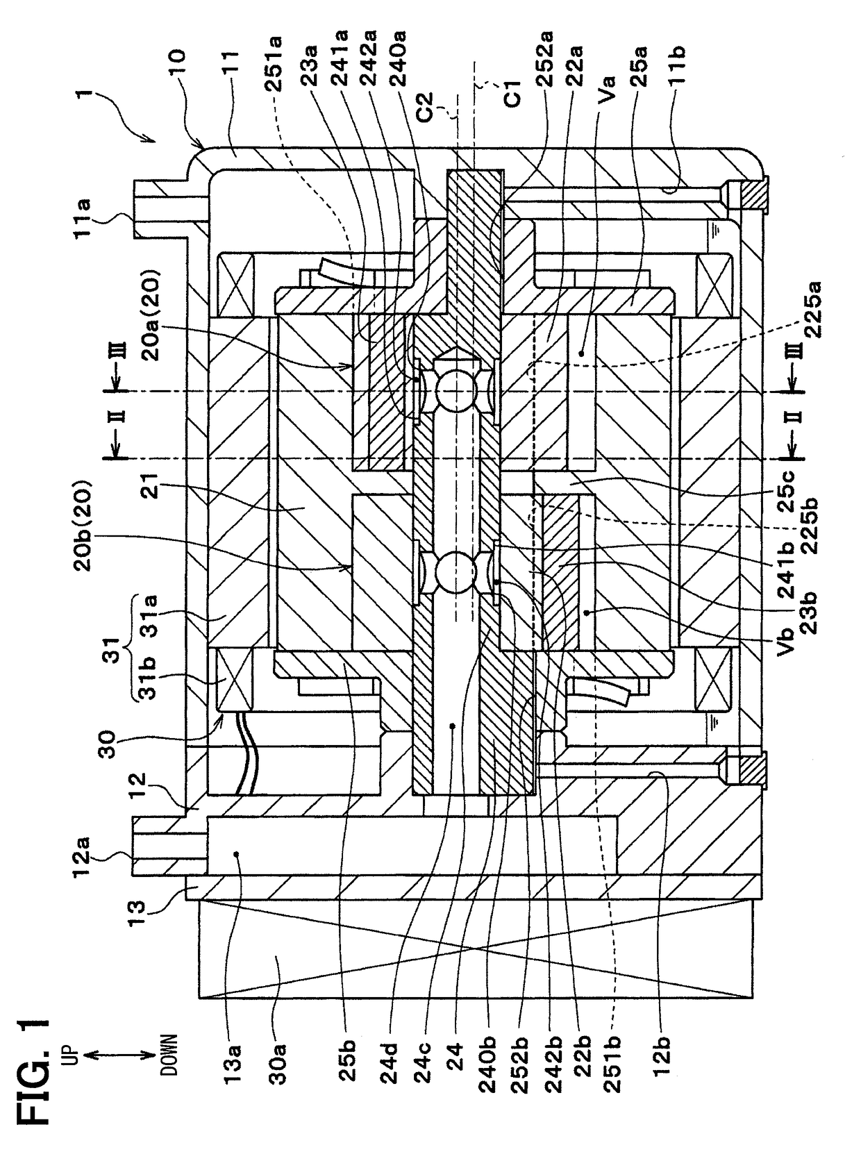
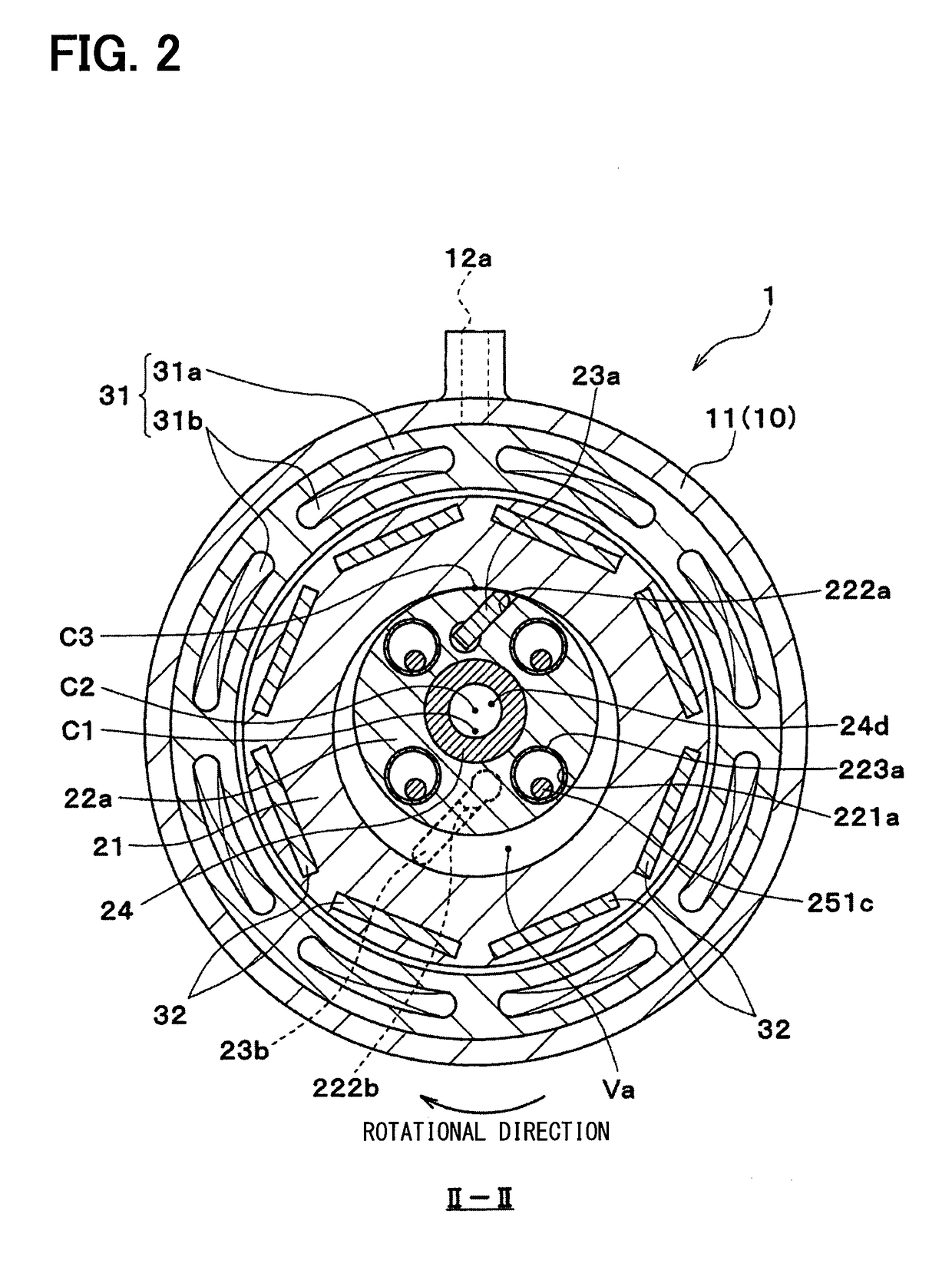
[0024]Hereafter, a first embodiment is described with reference to the drawings. A rotating cylinder type compressor 1 of this embodiment (hereafter referred as the compressor 1) is applied to a vapor-compression refrigeration cycle apparatus which cools air to be sent to a cabin in an air-conditioner for a vehicle. The compressor 1 compresses and discharges refrigerant which is a fluid to be compressed in the refrigeration cycle apparatus.
[0025]The refrigeration cycle apparatus adopts HFC base refrigerant (specifically, R134a) as a refrigerant, and defines a sub-critical refrigeration cycle in which the high-pressure side refrigerant pressure does not exceed the critical pressure of refrigerant. Furthermore, the refrigerant slightly contains a lubricating oil lubricating the sliding part of the compressor 11, and a part of the oil circulates through the cycle with the refrigerant.
[0026]As shown in FIG. 1, the compressor 1 is an electric compressor including a compression mechanism ...
second embodiment
[0113]As shown in FIG. 7, in the present embodiment, the compression mechanism part 20 is modified relative to the first embodiment. In addition, FIG. 7 is a sectional view corresponding to FIG. 3 which is explained in the first embodiment, and shows a sectional view of the first compression mechanism part 20a perpendicular to the axial direction. In FIG. 7, the same or equivalent portion as the first embodiment is attached with the same reference number. This is the same also in FIG. 8 to be explained below.
[0114]More specifically, a first hinge part 231a is formed at the outer circumference side end portion of the first vane 23a, in the first compression mechanism part 20a of this embodiment. The first hinge part 231a is supported by a groove portion formed in the inner circumference surface of the cylinder 21, and is swingable in the circumferential direction. For this reason, the vane 23 does not separate from the cylinder 21, and the inner circumference side of the first vane 2...
third embodiment
[0118]As shown in FIG. 8, the compression mechanism part 20 is modified in this embodiment, relative to the second embodiment. More specifically, in the first compression mechanism part 20a of this embodiment, the inner circumference side of the first vane 23a on the radially inner side of the first hinge part 231a is formed into a plate shape.
[0119]Furthermore, a first shoe 232a is arranged in the first groove portion 222a, and has a cross-sectional form (approximately semi-circle shape) in which a part of the circle is cut off, when seen from the axial direction of the central axis C1. The first vane 23a is interposed between the first shoes 232a. The length of the first shoe 232a in the axial direction is approximately the same as the first rotor 22a and the first vane 23a. The fundamental configuration of the second compression mechanism part 20b is the same as that of the first compression mechanism part 20a.
[0120]The other configuration and operations are the same as those of...
PUM
 Abstract
Description
Claims
Application Information
 - R&D
- Intellectual Property
- Life Sciences
- Materials
- Tech Scout
- Unparalleled Data Quality
- Higher Quality Content
- 60% Fewer Hallucinations
Browse by: Latest US Patents, China's latest patents, Technical Efficacy Thesaurus, Application Domain, Technology Topic, Popular Technical Reports.
© 2025 PatSnap. All rights reserved.Legal|Privacy policy|Modern Slavery Act Transparency Statement|Sitemap|About US| Contact US: help@patsnap.com


